FAQ
We will try to post frequently asked questions from previous versions of the project and from new questions on Ed Discussions here.
Questions from Ed
How to change render window size?
The relevant css for the application elements is in Component/style.ts. You can change the max-width and max-height attributes:
.anigraphcontainer{
    max-height: 95%;
    max-width: 95%;
    aspect-ratio: 1;
    border: black;
    border-radius: 3px;
    border-style: solid;
  }
Changing them from 95% to something smaller will make the drawing window smaller.
The Role of Materials When Rendering Objects in AniGraph:
In past years, students were sometimes confused about the role of "material" objects in AniGraph. Some of that confusion comes from the fact that materials represent shaders, which we don't cover until later on in the semester. In general, computer graphics systems rely on many parts, and we can't cover all of them at once, but you'll understand a lot more by the time you finish the course. The main thing to understand for now is that each material specifies a different procedure for coloring the pixels covered by certain geometry you send to the GPU.
For example, the LabCatFloatingHeadModel class in Example2 uses a custom material that colors geometry in using a texture of Lab Cat's face. But let's look at some more general examples to see how materials operate at a high level.
Materials Example
Here I provide a simplefied example of rendering with three different materials to hopefully clarify the role that materials play overall. Note that there are often multiple ways to accomplish the same effect in AniGraph, as with most graphics systems. The choice may depend on what you are trying to do. With this in mind, different examples in the code may demonstrate different approaches to the same problem, and you may find looking over these variations useful when solving problems in your project.
In the code below we see two materials used: one that simply assigns a solid color to the object being rendered, and another that interpolates colors defined at every vertex of the geometry. Read through the comments for more detail.
initScene(){
    let appState = GetAppState();

    // Lets create a polygon object and set it to have color data.
    // It will have color data by default if we create it with CreateForRendering, but we will be explicit here.
    let squareGeometry = Polygon2D.CreateForRendering(true);

    // Alternatively, we could create the polygon geometry and initialize attributes one at a time:
    // let  squareGeometry = new Polygon2D();
    // squareGeometry.initColorAttribute(); // initialize the color attribute

    // You can add geometry one vertex at a time
    squareGeometry.addVertex(V2(0,0), Color.Random());
    squareGeometry.addVertex(V2(2,0), Color.Random());
    squareGeometry.addVertex(V2(2,2), Color.Random());
    squareGeometry.addVertex(V2(0,2), Color.Random());


    // The rgba material will use the colors assigned to each vertex
    let rgbaMaterial = appState.CreateRGBAShaderMaterial();

    // The basic material will just assign one global color to the object
    let basicMaterial = appState.CreateBasicMaterial(Color.FromRGBA(0.0,1.0,0.0,1.0));

    // Let's make two polygon models
    let polygonRGBA = new Polygon2DModel();
    let polygonBasicShader = new Polygon2DModel();

    // Same geometry for both
    polygonRGBA.setVerts(squareGeometry)
    polygonBasicShader.setVerts(squareGeometry);

    // Different materials. We will use the RGBA material for one and the basic material for the other
    polygonRGBA.setMaterial(rgbaMaterial)
    polygonBasicShader.setMaterial(basicMaterial);

    // Let's put the rgba one on the bottom left and the basic one on the top right
    polygonRGBA.setTransform(new NodeTransform2D(V2(-2,-2)))
    polygonBasicShader.setTransform(new NodeTransform2D(V2(2,2)));

    // Add them to our scene
    this.addChild(polygonRGBA);
    this.addChild(polygonBasicShader);

}
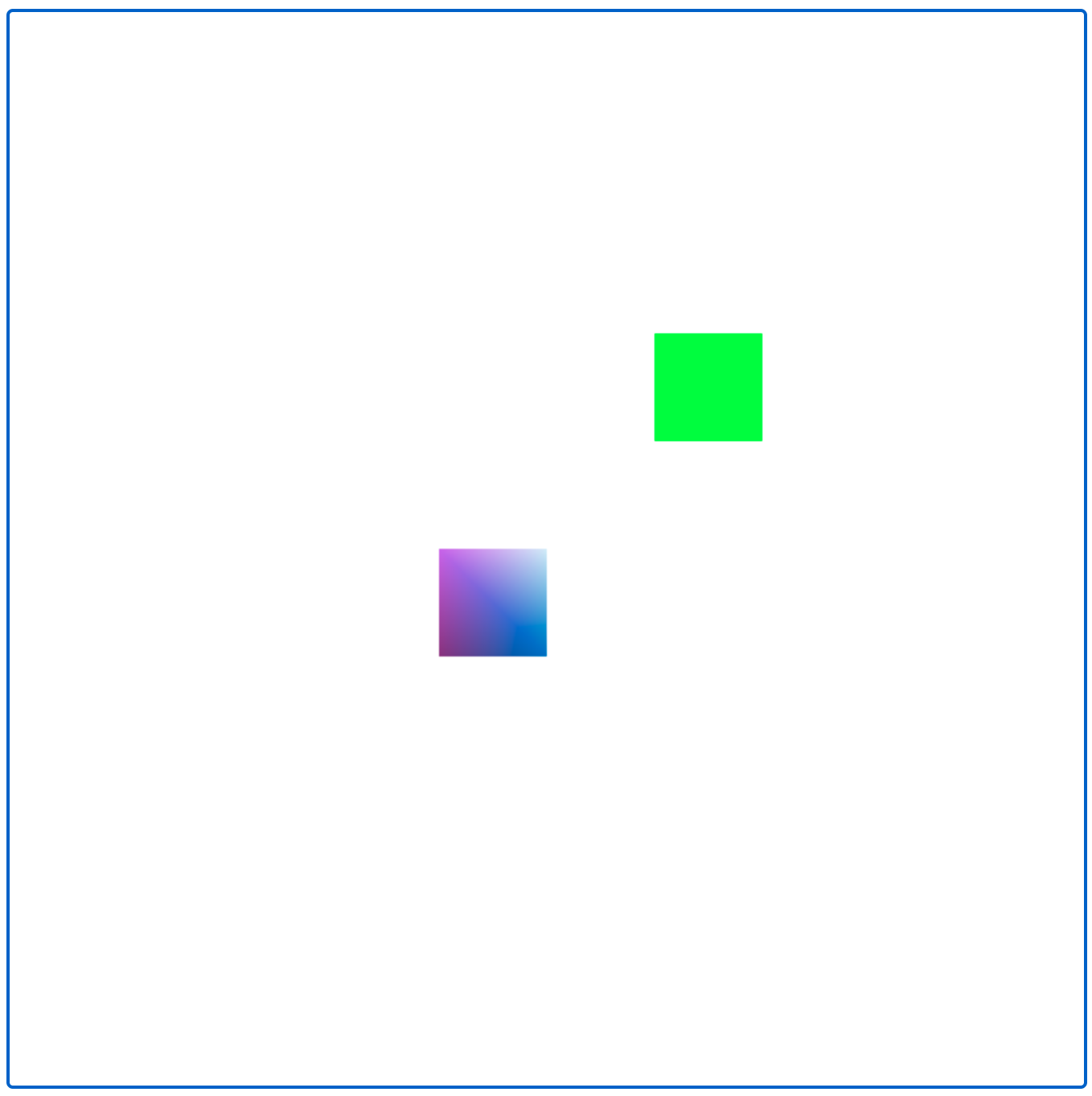
The above code renders to the image below. Note that the colors of the bottom left shape are randomized, so they may be different every time you run things:
Textured Materials
Let's say we want to add a textured object to the code above. To do this, we will need to load two things: a material model that we can use to render textures (don't worry too much about this for now), and a texture to actually render. We can load these in PreloadAssets functions, which you will find in SceneModel and NodeModel various classes. Here we will add it to this function in our scene model class:
export class MainSceneModel extends Creative1SceneModel{
    static exampleTexture:ATexture;

    async PreloadAssets(){
        await super.PreloadAssets();

        // Load the material model. This only needs to be called in one `PreloadAssets()` call anywhere in your program, so depending on what else you load, it may already be called elsewhere. It should be fine to call multiple times, though.
        await GetAppState().loadShaderMaterialModel(DefaultMaterials.TEXTURED2D_SHADER);

        // Load your texture here by providing a path to your image relative to the public folder.
        // png and jpeg should both work
        MainSceneModel.exampleTexture = await ATexture.LoadAsync("./images/calvin-and-hobbes.jpg");
    }
    ...
    ...
Now, when we initialize our scene, we can create a material that expects a texture and give it our loaded texture. For example, if we add the code below to the initScene function we wrote in the previous example:
initScene(){
    let appState = GetAppState();

    // Create the textured material
    let texturedMaterial = appState.CreateShaderMaterial(DefaultMaterials.TEXTURED2D_SHADER);

    // Set the texture to the one we loaded
    texturedMaterial.setTexture("color", MainSceneModel.exampleTexture)

    // Set the geometry to geometry with texture coordinates. We will learn more about this later in the course.
    let texturedSquareGeometry = Polygon2D.SquareXYUV();

    // Create the model
    let texturedQuad = new Polygon2DModel();

    // Set the geometry and material.
    texturedQuad.setVerts(texturedSquareGeometry);
    texturedQuad.setMaterial(texturedMaterial);

    // Set its transformation
    texturedQuad.transform.position = V2(3,-3);
    texturedQuad.transform.scale = V2(3,2);

    // Add the quad
    this.addChild(texturedQuad);

    ...
The scene would render as follows:
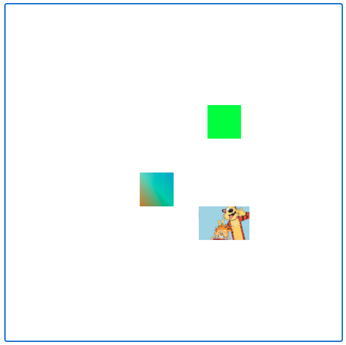
Note that we scaled our geometry to have the same aspect ratio as our image so that the image wouldn't appear distorted. If we did not perform this scale then our image would look a bit squished, as the entire image maps to the entire geometry.
Rendering Lines
Raster-based graphics don't natively support lines. Technically, to render a "line" you would actually render a long skinny rectangle. That being said, AniGraph and Three.js have some helper code to make this easier.
First, note that you will need to create a line material. This can be done once in your view class and used for all of your lines.
this.lineMaterial = ALineMaterialModel.GlobalInstance.CreateMaterial();
Then, to create a graphic element that is a sequence of lines,
// for VertexArray2D, CreateForRendering(...) will create position and color attributes for the geometry by default
let verts = VertexArray2D.CreateForRendering();
// When we add vertices we can now provide a color for each vertex
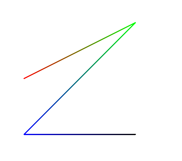
verts.addVertex(V2(-5,0), Color.FromRGBA(1.0,0.0,0.0,1.0));
verts.addVertex(V2(5,5), Color.FromRGBA(0.0,1.0,0.0,1.0));
verts.addVertex(V2(-5,-5), Color.FromRGBA(0.0,0.0,1.0,1.0));
verts.addVertex(V2(5,-5), Color.FromRGBA(0.0,0.0,0.0,1.0));
// Now lets make a new line graphic
let line = new ALineGraphic();
// set its geometry and material
line.init(verts, this.lineMaterial);
// add it to the view
this.registerAndAddGraphic(line);
The vertices in this case will be interpreted as defining a sequence of line segments. The code above renders something that looks like this: