
|
|
||||||
![]()
Vehicle Platform Mission Specific Payload and Sensors Mission Strategy
![]()
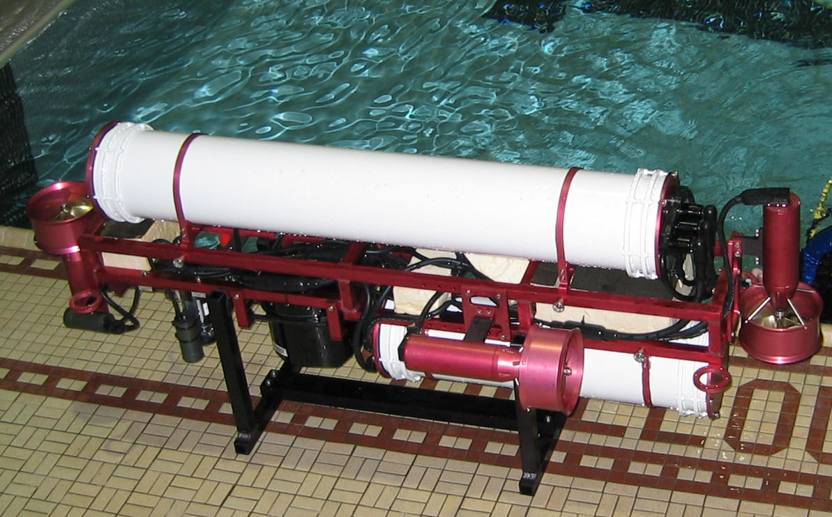
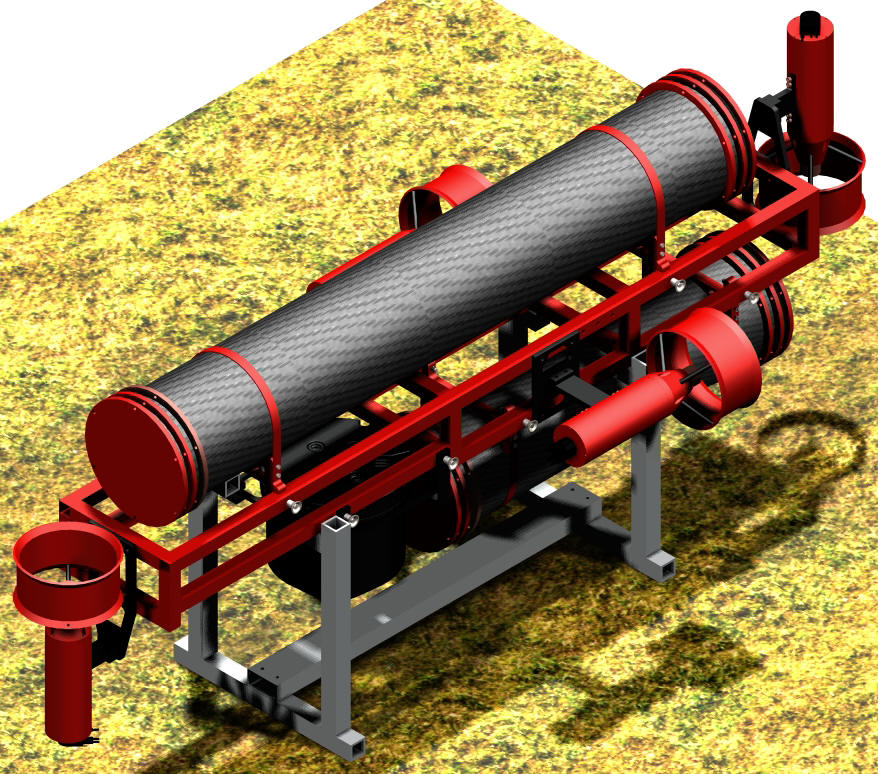
CUAUV 2003 Autonomous Vehicle Platform
We’ll start of with some philosophy…
The overall design philosophy of the vehicle is to make a robust and expandable underwater vehicle platform. As been the fact in previous years, the design process starts well before final competition rules are published. We did not make guesses on what the mission would be, but instead design a vehicle with a good amount of flexibility built into it. No part of this vehicle is over-designed, but rather it is designed to be adaptable to any mission’s need.
Introducing our ‘submarine’
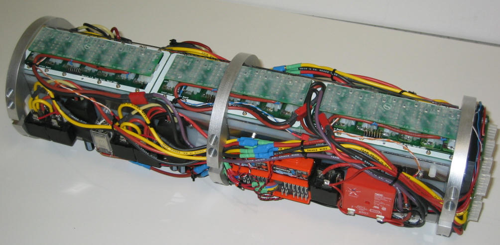
The hardware platform is based on the now-classic Cornell’s twin-hull-on-aluminum-frame concept. The central frame provides easy access for mounting sensors and any other payload. The larger top hull will house the vehicle electronics, while the bottom hull contains the vehicle’s batteries and motor controllers. The combination of relatively high buoyancy on the top hull and greater weight on the bottom hull gives the vehicle an excellent static stability on the pitch and roll axes.
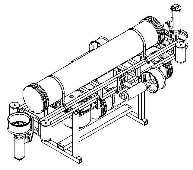
The top and bottom hulls are coupled to the frame by means of a spring loaded locking pin. The vehicle can be dismantled into a frame and two tubes in a matter of minutes for easy transport and shipping.
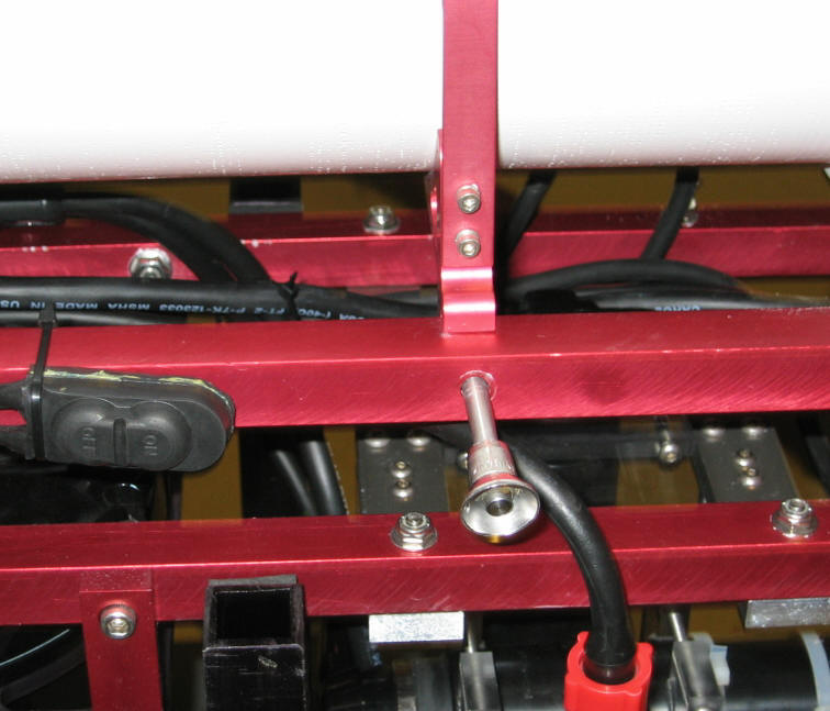
The vehicle is designed and further trimmed to be slightly buoyant (for safety reasons). Two thrusters in the fore and aft provide altitude control, while another two provides horizontal propulsion as well as directional control. A hermetically sealed kill switch will disconnect power to the thrusters when activated.
The bottom fore section of the vehicle is reserved for mission specific sensors and payloads. A Doppler Velocity Log (DVL – explained in later section), mounted in this section, is considered an integral part of the vehicle platform as it provides crucial information to be used by the vehicle’s feedback control system and environmental monitoring.
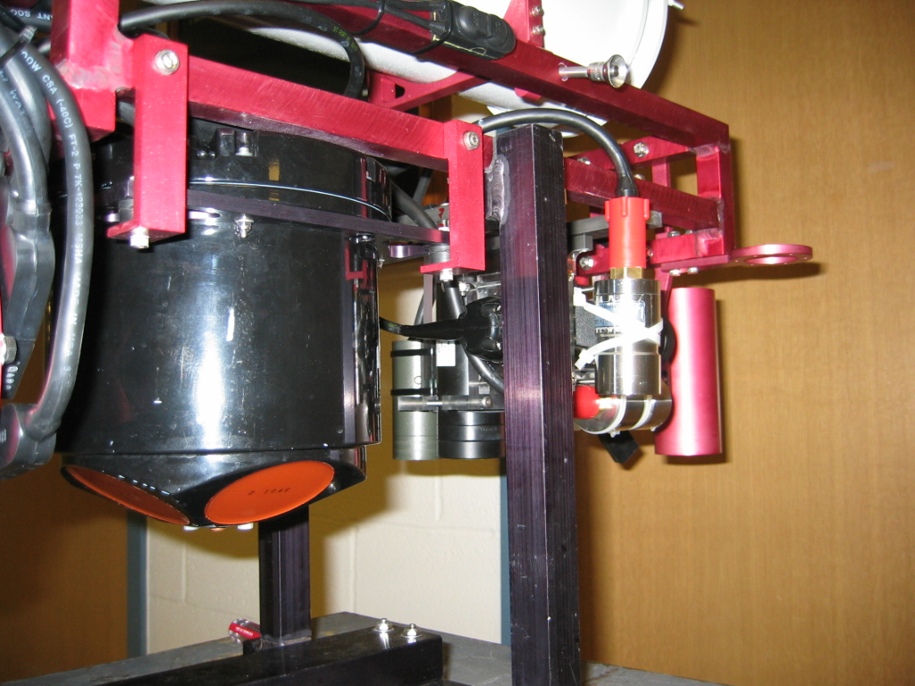
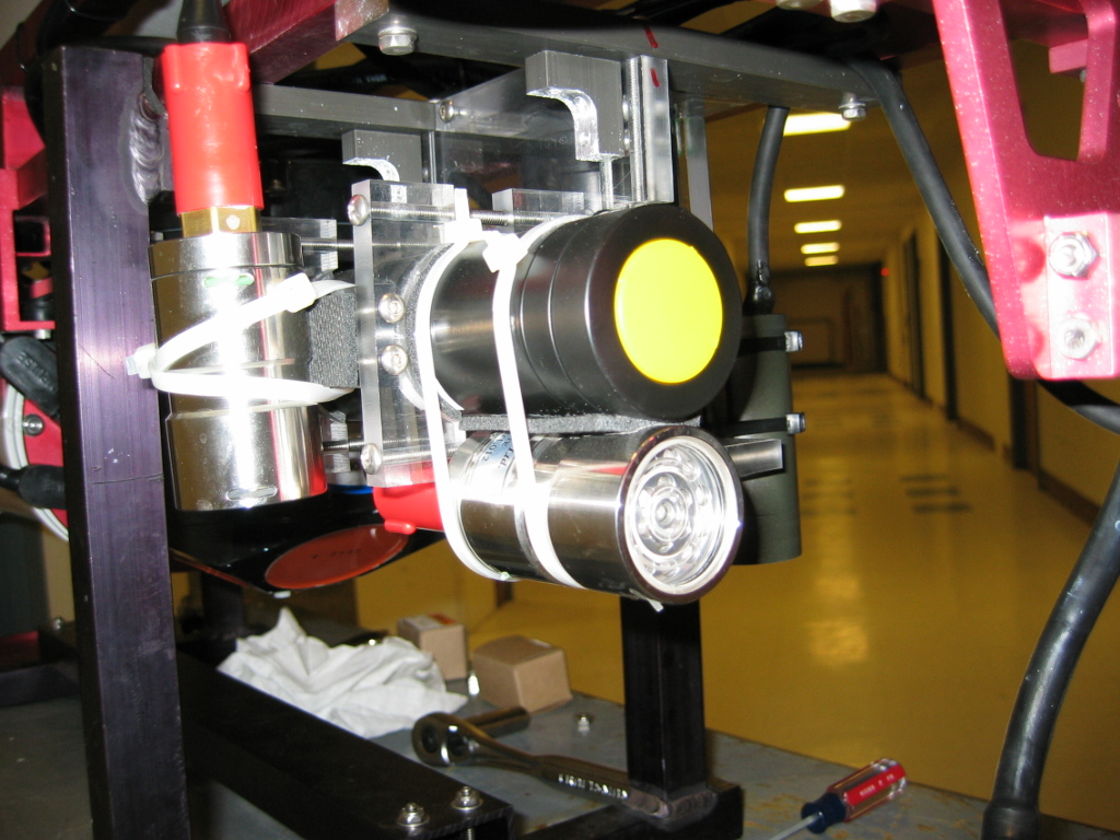
Propulsion - Thrusters
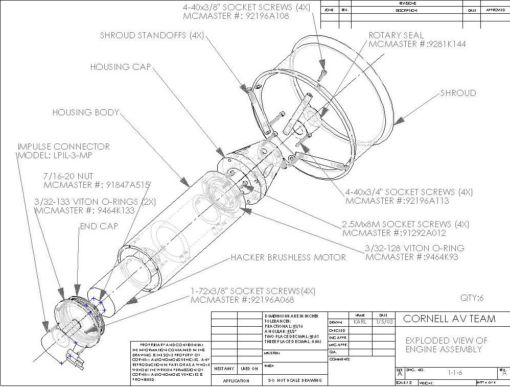
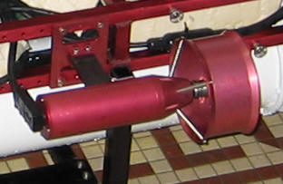
Each thruster is driven by a Hacker brushless motors running at ~28V. The thruster shaft mounts to a propeller designed specifically for use in water through a rotating shaft seal, allowing a watertight rotating connection. An aluminum shroud mounts to the thruster body to protect against accidental contact with the prop. Two threaded holes on the thruster wall allow for easy mounting with standard hardware. The rear of the unit mounts a single three-pin connector designed for submersible use, and a dual O-ring seal ensures that the connector end is watertight.
Since brushless motors are irreversible, relays are put inside the lower hull to provide this essential feature. The motors and the relays are then controlled by a single mini SSC motor controller – also inside the bottom hull. The SSC communicates to the on-board computer using a single serial line. This separation of control signal and high-power motor-drive electronics provide good electrical decoupling from the relatively noisy motors and drivers from the electronics inside the top hull.
Software driver tabs to the SSC is designed to hide the physics of the thrusters – that they are reversible only through relay control – to provide a simple -100% to 100% thruster power control to higher level feedback and AI control.
Next: Connection Systems and Batteries =>
Skip to Mission Specific Payloads and Sensors
![]()