
|
|
||||||
![]()
Vehicle Platform Mission Specific Payload and Sensors Mission Strategy
![]()
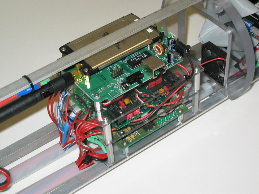
"The Rack"
All electronics in the top hull is mounted on one streamlined electronics rack.

All wiring in the rack is routed through two wiring conduits under the rack, giving a clean and organized appearance.

Each PC-104 stack is mounted on the rack. The hard drive is mounted below the PC-104 stack on a removable ‘tray’

One end of the tray connects to blind mount connectors to a semi permanent endcap with external connectors.

The other end of the rack is the access end. It features the following : an LCD panel to show battery and computer status, a master power switch, one switch for each computer, and a 50-pin header for KVM (Keyboard-Video-Mouse) access to each computer as well Ethernet access to the on-board switch.


More processing power !
As part of the initial design, the vehicle supports two independent PC-104 computer stacks, as well as the necessary support equipment to allow them to communicate and interface properly with the rest of the vehicle. Each system operates from an independent supply, so that any failure modes will be limited to a single system.
The two-computer solution was prompted by experiences in previous years with vision processing. Effective visual detection depends on the capture and processing of as many frames as possible by the host computer. Unfortunately, operating a computer in this fashion almost universally degrades performance for other applications on the system. While some sensors, such as low-bandwidth serial links are not overly degraded, others, including the hydrophones, operate at higher speeds and require relatively complex analysis of their own. While not as intensive as vision, the other necessary components of the system do not coexist well with such a processor intensive application.
Because of this, the decision was made to split the processing across two systems. One system is relatively slow and lower power, but is more than suitable for the lower-speed processing requirements. The second is a faster system dedicated to vision processing This division of labor has helped to achieve good system performance and response times without compromising mission critical cababilities. Ultimately this would provide the vehicle with the capability to tackle a more wide-ranging and demanding mission profiles.
The first computer is a Technoland 800MHz crusoe that serves as the main I/O and control processor for the submarine. This system is responsible for handling sensor inputs other than the cameras, acting as a centralized, network-accessible repository of system state, and running the control programs (such as PID) necessary for proper operation.

The second computer is a Pentium III based Jaguar platform whose sole purpose is to capture and process video information from the cameras as quickly as possible. It is configured with a Sensoray frame grabber (based on the BT848/878 chipset) capable of accepting two NTSC video inputs and converting them into YUY2 or RGB images suitable for computer analysis. Captured video is processed entirely on the Jaguar, with the only required communications achieved through a state synchronization protocol.

To deal with the multiprocessor system, appropriate hardware and software infrastructure is implemented to maintain programming simplicity while harnessing the processing power and redundancy provided. Independent supply for each computer ensures that failure in one computer would not propagate to the other. A 4-port Ethernet switch in PC-104 form-factor is integrated in the electronics rack to provide bidirectional communication between the two computers as well as provisions for external Ethernet access and also for a wireless access point.
Both computer systems run GenToo Linux (www.gentoo.org). On top of this we run a hybrid system, comprised of a replicated shared state server and an RPC backbone for state synchronization. This guarantees that any system has a local copy of variables that are accessible through a fast shared-memory mechanism, while also allowing for networked operation to support multiple computer systems.
The structure of the system drivers, conversion processes, and other functions is a good illustration of the benefits of this system. A driver interface may be produced as a simple process stub that reads from the interface in question and writes to the shared memory variables, or that reads from shared memory and writes to a device interface. One may also have a process that reads from shared memory and writes back to shared memory.
The attractive feature of this model is that the shared memory system contains all of the important system state information. Thus, the driver stubs may be modified, re-compiled, and re-started dynamically. This feature has greatly simplified software development and fine tuning for the system.
Doppler Velocity Log
The RDI DVL unit uses a correlation analysis of four independent sonar beams at known angles to calculate velocity, and thus gives both velocity and distance measures. In addition, our unit contains a magnetic compass for heading data, and was refitted to include a pressure sensor for depth measurements. The DVL feedback forms the core of the sensors responsible for the vehicle’s feedback control system.

Next: Mission Specific Payloads and Sensors =>
<= Back: Connection Systems and Batteries
![]()