
|
|
||||||
![]()
Vehicle Platform Mission Specific Payload and Sensors Mission Strategy
![]()
Mission Specific Payloads and Sensors
The following section will describe the current vehicle configuration for the 6th annual International Underwater Vehicle Competition. Complete rules and description of the competition can be obtained here (www.auvsi.org)
Hydrophones – Acoustic Direction Finding System
The target of this year’s mission will be marked by an acoustic beacon operating at one of 6 possible frequencies. The beacon will emit a ‘ping’ once every second – staggered between the six frequencies.
Direction finding can be easily achieved by time
difference measurement on array of acoustic transducers (hydrophones). The
difference in time-of-arrival between two  transducers
will correlate directly –with a known velocity of sound underwater- to the extra
distance that the acoustic wave needs to propagate from one transducer to the
other from a particular beacon bearing. Given a known geometry of the transducer
array, one can easily estimate the bearing of the beacon.
transducers
will correlate directly –with a known velocity of sound underwater- to the extra
distance that the acoustic wave needs to propagate from one transducer to the
other from a particular beacon bearing. Given a known geometry of the transducer
array, one can easily estimate the bearing of the beacon.

To achieve the direction finding goal, we designed and implemented a digital-signal-acquisition module. Each module comprises of a variable gain amplifier, an analog to digital converter and a Texas Instruments’ TMS320C5509 Digital Signal Processor. Each module is synchronized using a single master clock and can communicate to a host computer by means of a USB bus.

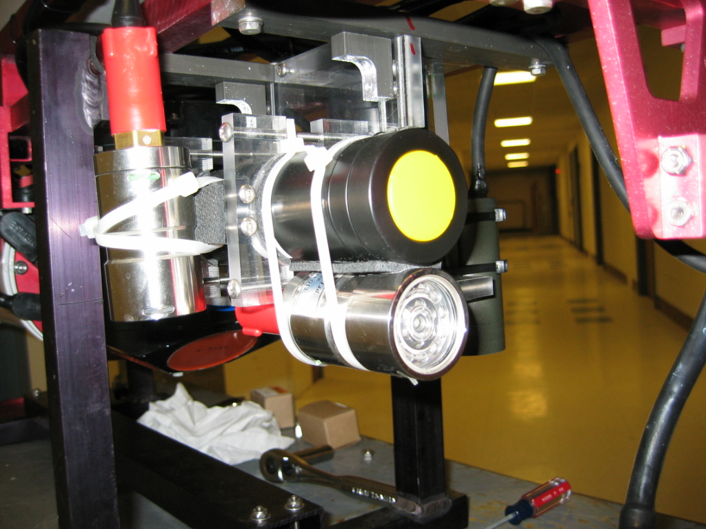
One DSA modules are connected directly to a hydrophone and placed inside its own water tight compartment (‘cans’). This is done to minimize interference pickup from noise sources integral to the vehicle, such as motor noise, by converting the analogue signal to digital data stream as early as possible.

Four of these transducer-data-acquisition modules are placed on the four extreme corners of the vehicle. By giving a maximum spatial separation between the transducer we can minimize the percentage error due to the system’s absolute limitation on time measurement (conversion clock jitter and sample rate resolution).
Each of the modules will filter the data to a selected pass-band frequency, and detect for the presence of a ‘ping’. Upon detecting a ping, a snapshot of the waveform is sent to the one of the on-board computer through a USB hub. Once that data is received, the computer performs a cross-correlation analysis of the data from all four hydrophones. This gives a relative delay matrix for the system, from which one can extract the angular bearing of the acoustic signal.
The individual module by itself presents a very expandable and compact data acquisition solution. The variable gain amplifier gives great flexibility in adapting to different signal amplitude and also to compensate for discrepancies in the response of each transducer compared to the other.
Even to a larger extent, the whole analog front end is mounted on a separate board from the DSP, giving the ability to redesign the analog front end to adapt with a different input requirement without redesigning the signal processing and USB link to the computer. The USB bus is ultimately expendable up to 128 different endpoints at data rate of upto12Mbit/s. With proper buffering, synchronization between data acquisition modules can also be kept with higher device count. The C5509 DSP processor is capable of up to 120 millions instruction per second, or up to 240 millions multiplications per second (due to the dual MAC architecture), opening vast possibility for real time signal processing using these modules.
Each Digital Signal Acquisition module – ADC/DSP stack – costs about $200 to build and manufacture, and takes about 100 mA of current at 5V.
Altimeters
Two Tritech Altimeters are employed in this year’s vehicle to aid in accomplishing the mission.

One altimeter faces downward for accurate altitude measurement with a narrow cone. This is necessary in the target approach phase, where the 4 beams of the DVL will diverge around the target area instead of measuring the altitude from the target.
The second altimeter faces forward for collision avoidance and possibly wall-following.
Vision Processing
Two color video cameras are mounted on the vehicle – one faces downward, and the other faces forward. Each camera is assisted by a TriTech LED lights.


The 2003 CUAUV vision software correctly identifies the lines on the arrows,
which will be used for real-time analysis of the decision point. The line which
intersects the LED light will be used to make the decision.
![]()