 6. Face Tracing
The edges can be adjusted in real-time when adding
new vertexes and the related edges are splited if necessary. However,
the face information is lost after the process. Although a topology
can be described only by the network of vertexes and edges, the face information
comes to handy when implementing the algorithm on popular graphic libraries,
such as OpenGL. This project uses OpenGL as the main resource for
constructing the visual interface, so a special algorithm is created to
reconstruct the entire face lists from the set of vertexes and edges provided
after the PM1 and PM2 are merged on the common model with the Weiler’s
algorithm.
Face Tracing : 3 Steps
1. Find the vertex list of all the polygon faces
2. Adjust Vertex list order of the face to be
counter-clockwise
3. Reduce all polygons to triangles
1. Face Tracing Algorithm
For Each Egde
Use an iterative deepening
search to find the minimum number of edge required to form a polygon face.
Repeat if desired (until each
edge is marked exactly twice)
|
Figure 8 : Psuedocode for Face Tracing
Algorithm
This is an abbreviated version of the actual algorithm.
Some special cases need to be considered, such as a polygon forming inside
another polygon with same number of edges. Breadth-first search can
be used instead of iterative deepening search. It’s faster at the
cost of memory space required.
2. Face adjustment
For rendering purposes, we would like to have
the normals of all faces facing outward. We use the right-hand rule
(counter-clockwise) to determine the direction of the normal. Using
the vertices of one of the mapped model, we can calculate the normal of
a polygon face and the vector from the center of the model to the face.
Calculate the dot product of the two, we can determine if the polygon is
facing outward or inward. If the polygon is facing inward, we simply
reverse the order of the vertex list of the polygon face.
3. Triangles-only club
We need to make sure all polygon faces are triangles
since a triangle is always flat. This is done for rendering purpose
also. We used a very simple method of reducing polygon to triangles.
Take any vertex of a face and draw a line to the rest of the vertices.
We can use this method since we are guaranteed to have convex polygon faces.
7. Polygon Interpolation
Once all correspondence is established.
Both objects will have the same number of vertices and faces. Faces
in PM1 are mapped to faces in PM2. The next step is just to interpolate
from one to the other. We explore 3 schemes of interpolation.
1. Linear Symmetric Interpolation
This is the simplest scheme. The coordinates
X, Y and Z are linearly interpolated from PM1 to PM2 with the same rate.
The result is similar to putting the air to one object and it inflates
to become the other.
2. Non-Linear Symmetric Interpolation
The variant of this scheme is that the coordinates
X, Y and Z are non-linearly (exponentially) interpolated from PM1 to PM2,
but still with the same rate. The result is similar to putting the
air to one object and it inflates to become the other. The different
is that the object morph slowly at the beginning and fast at the end.
3. Non-Linear Non-Symmetric Interpolation
The variant of this scheme is that the coordinates
X, Y and Z are not interpolated with the same rate. The result is
non-symmetric transformation.
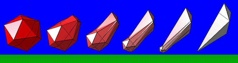 Figure 9 : Linear Symmetric Interpolation
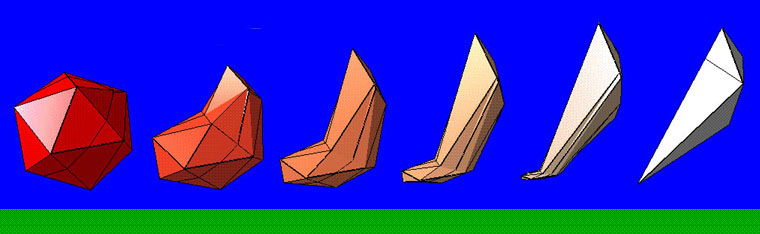 Figure 10 : Non-Linear Symmetric Interpolation
8. Applications
All examples can be downloaded. The following
keys are needed to activate the morphing. Press "O" to indicate the
object. Press "F" to forward the morphing sequence. Press "R"
to reverse the morphing sequence.
 Figure 11 : Complex Object Morphing
(Download
Animation Program)
Figure 11 : Complex Object Morphing
(Download
Animation Program)
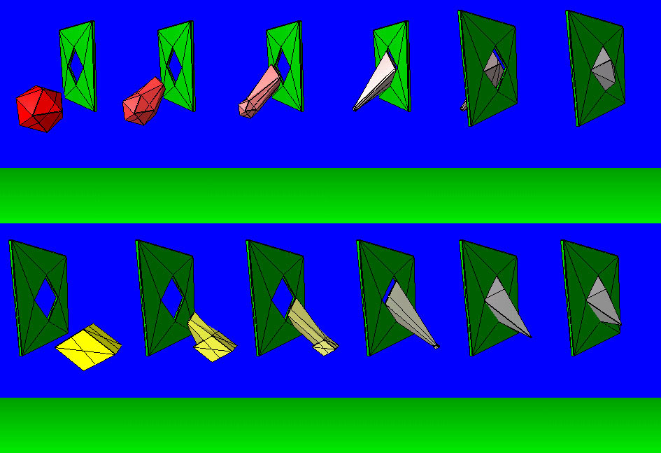 Figure 12 : Morph Across Window
(Download
Animation Program)
Figure 12 : Morph Across Window
(Download
Animation Program)
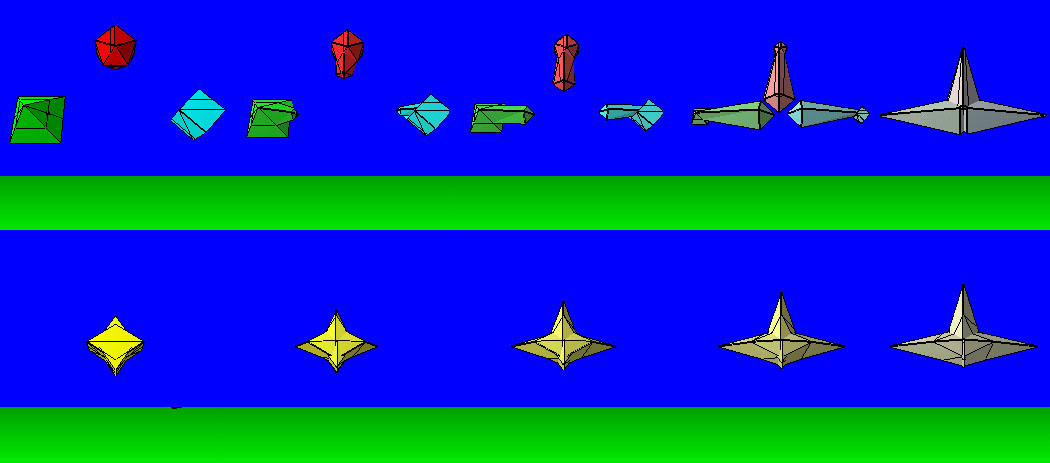 Figure 13 : Object Integration and
Disintegration
(Download
Animation Program)
Figure 13 : Object Integration and
Disintegration
(Download
Animation Program)
9. Source Code Distribution
White Paper version can be downloaded from 3DMorph.doc
file. All sources are stored in 3DMorph.zip
file. They are tested on WinNT4.0 and Win95 platform. OPenGL1.0
which usually come with WinNT and Win95 is needed for graphic library.
Although Microsoft Developer Studio VC++ version5 is used, any C compilers
such as GNU or BORLAND should be able to use and developer platform.
10. Summary
Future research need to be done to develop projections
for general concave polyhedra with holes. The new algorithm
which can work under discontinuity of object surface need to be explored.
The idea would be that the desired projection of the objects and subsequence
polygon mapping could be carried out for the objects with the same number
of holes.
This project is a part of Multimedia class -
CS631 at Cornell University. Any comments on the paper will be very
much appreciated. For more information, please contact the author.
References
[1] Weiler, K. Polygon
Comparison Using a Graph Representation. Proceedings of SIGGRAPH
'80 (Seattle, Washington, July 1980). In Computer Graphics
14, 3, (Aug. 1980), 10-18.
[2] J, R. Kent, W. E.
Carlson and R. E. Parent, Shape Transformation for Polyhedral Objects.
In Computer Graphics (SIGGRAPH'92 proceedings), volume 26, pages
47-54, July 1992.
[3] Kent, J, Parent, R. and
Carlson, W. Establishing Correspondences by Topological Merging:
A new Approarch to 3-D Shape Transformation. Proceedings of Graphics
Interface '91 (Calgary, Alberta, June, 1991) 271-278.
[4] Foley, J., A. van Dam,
S. Feiner and J. Hughes, Computer Graphics - Principles and Practice, Addison-Wesley
Publishing Company, Inc., Reading, Massachusetts, 1990.
[5] Neider, J., Davis, T. and
Woo, M. Polygon Construction and Rendering Scheme. In OpenGL
Programming Guide, The Official Guide to Learning OpenGL, Version 1.1,
Addison Wesley Public Company, January 1997.