
A4: CPU Simulation
Instructions: Remember, all assignments in CS 3410 are individual. You must submit work that is 100% your own. Remember to ask for help from the CS 3410 staff in office hours or on Ed! If you discuss the assignment with anyone else, be careful not to share your actual work.
The assignment is due via Gradescope at 11:59pm on the due date indicated on the schedule.
Submission Requirements
For this assignment, there are two files to submit to Gradescope:
logic.cwith the listed functions all implemented.tests.txtwith all of your test cases in the correct format.
Restrictions
- You may not use any additional include directives.
- Please only change
logic.c. Changes to other files in the starter code will not be reflected in your submission.
Provided Files
The following files are provided in the release:
runner.c, which handles I/O and the overall structure of the simulator.hash_table.c, which is an implementation of a simple hash table to simulate memory.hash_table.h, which is the above’s associated header file.logic.c, which includes the five functions you will implement in this assignment.logic.h, which is the above’s associated header file, but also has usefuldefinemacros and variable declarations.Makefile, which will appropriately compile and link the above to produce an executable,runner.example-tests.txtwhich has some example tests (in the correct format) that your executable should pass.test_parser.pywhich provides utilities for parsing and running your correctness tests.
The only file among these that you will modify is logic.c.
Getting Started
To get started, obtain the release code by cloning your assignment repository from GitHub:
git clone git@github.coecis.cornell.edu:cs3410-2026sp-student/<NETID>_cpusim.git
Replace <NETID> with your NetID. All the letters in your NetID should be in lowercase.
Overview
In this assignment, you will implement a subset of the 64-bit RISC-V 64 instruction set. To gain a better understanding of control logic, processor architecture, and how assembly language functions, you will simulate the steps—Fetch, Decode, eXecute, Memory, Writeback—of a simple single-cycle processor. You can read more about these steps in the lecture notes on RISC-V, Architecture, RISC-V Memory, Control Flow, and Logic.
The program takes assembled RISC-V machine code into standard input. We handle the I/O and break the instructions down into an array of uint32_t values, named instructions. instructions[0] has the 32-bit encoding for the first instruction, and generally, instructions[PC / 4] has the 32-bit encoding for the PC / 4 + 1st instruction (i.e., the instruction at address PC in the input file). The instruction encodings follow the standard that is specified in the RISC-V ISA manual, which you can find on our RISC-V reference page and more general RISC-V resources.
After the instructions are fed into the program, while the program counter (divided by 4) is less than the static instruction count, it will continuously, in order, call the functions fetch(), decode(), execute(), memory(), and writeback().
Each of these 5 functions passes information to the next stage. fetch() will pass the current instruction to decode(), which will pass relevant information to execute(), which will pass other information to memory(), which will pass more information to writeback(), which will update the registers and the program counter. The relevant information is stored in a struct called info_t, which has space for 6 integer variables. It is up to you to decide exactly what information to store in the info_t struct, and no stage will require all integer variables to run.
Warning
The
info_tstruct is meant as a container for arbitrary bits. We have named the variables within the struct to suggest to how you may use them in a straightforward manner, but this scheme is not enforced. There are multiple valid ways to use its fields to represent the relevant state. You will likely use theinfo_tstruct in entirely different ways for each of the four stage → stage communication steps. Note, that you can just return theinfo_tstruct directly (pass by value), no need to malloc/free it.
The 32 general-purpose registers are simulated as an array of 32 uint64_ts. The starter code initializes all of these to 0.
Memory is simulated as a hash table, data, that maps from uint64_t to uint8_t. The keys are addresses, and the values are the data stored in memory. This means we map a 64 bit address to a single byte in memory, and thus when storing or loading words/double words you need to store/load multiple bytes at a time.
An implementation of a hash table is provided in hash_table.c and hash_table.h. All key (address) → value (data) mappings are effectively initialized to 0, as the ht_get() function returns 0 when the key is not found.
Warning
Use the little-endian byte order for your simulated memory. For example, when storing an 8-byte value to address
a, store the least-significant byte ataand the most-significant byte at addressa+7.
Assignment Outline
- Work out a high-level plan and implement
addi,andi,ori, andxori, detailed in Task 0. - Implement the rest of the instruction subset, detailed in Task 1.
- Create a thorough test suite that you will submit, specified in Task 2.
Implementation
Task 0: Getting Started
Design Plan
As stated in the overview, one of the goals of the assignment is to familiarize yourself with the important steps in a simple five-stage processor. The figure below may be used as reference.
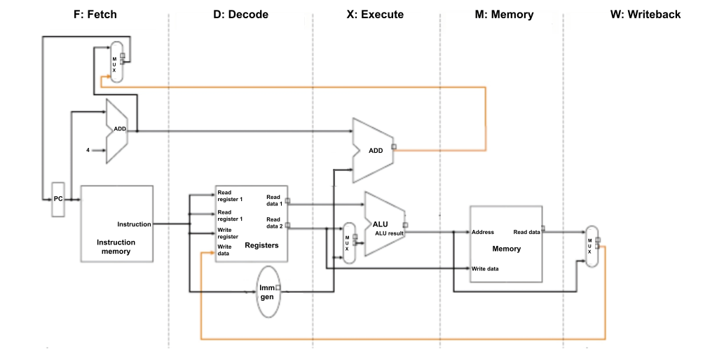
The five stages of the processor that you simulate are:
-
Fetch an instruction from main memory. The PC (Program Counter) holds the address of the instruction to fetch.
-
Decode the instruction into relevant parts that the processor understands, and read the values from the requested register(s). Things to consider: What information is important to extract from an instruction? How should we generate the correct immediate value from the bits in the instruction? How do we single out bits that differentiate instructions—what makes
lwdifferent fromswor fromsb? -
Execute the arithmetic operation specified by instruction to determine its resulting value to be used in later stages.
-
Access memory (here simulated as a hash table) to load/store data, if necessary. Things to consider: How should the stage differentiate bytes vs. words vs. double words? When should this stage sign-extend or zero-extend values when loading and storing?
-
Write back a new value for the PC, which should—except in the case of a branch—increment by 4 after every cycle, since each instruction is expressed with 4 bytes. Also, write back a newly computed value to the register file, if necessary. Things to consider: When should we write to the register file at all? What should we increment the PC by?
Warning
In some processor designs the program counter is updated before the writeback stage (e.g., in the execute stage) to save on the branch prediction penalty. However, in this assignment we will be updating the program counter in the writeback stage to simplify our simulation logic a bit.
Warning
Remember that the
x0(otherwise known aszero) register has a special behavior in that it should always be equal to zero, no matter what operations are done on it. An example is that even after the instructionaddi x0, x0, 1is run,x0should remain equal to zero.
Create a high-level plan for what each function should do and what information it should pass to the next stage. For example, the Memory stage is the only one that accesses memory, and the Decode stage will be the only one that deals with bit-level slicing of the actual instruction word.
Warning
While it would certainly be possible to simulate everything in one function, implementations that are not faithful to the purpose of each stage will incur penalties.
Implementing four I-type Instructions
Now that you have a plan, let’s walk through four instructions.
-
addi rd, rs1, immis implemented as:Registers[rd] = Registers[rs1] + Sign-extend(imm) -
andi rd, rs1, immis implemented as:Registers[rd] = Registers[rs1] & Sign-extend(imm) -
ori rd, rs1, immis implemented as:Registers[rd] = Registers[rs1] | Sign-extend(imm) -
xori rd, rs1, immis implemented as:Registers[rd] = Registers[rs1] ^ Sign-extend(imm)
Consult the RISC-V reference page to see the encodings for these instructions. Since all of these are I-type instructions, they share the same encoding structure:
| 31 – 20 | 19 – 15 | 14 – 12 | 11 – 7 | 6 – 0 |
|---|---|---|---|---|
| imm[11:0] | rs1 | funct3 | rd | opcode |
The reference also tells us the values of the opcode and funct3 fields:
| Instruction | opcode | funct3 |
|---|---|---|
addi | 0010011 | 000 |
andi | 0010011 | 111 |
ori | 0010011 | 110 |
xori | 0010011 | 100 |
The fetch stage will get the instruction
at index PC / 4. Then, for addi, andi, ori, and xori instructions, the argument to the decode stage will be a uint32_t whose binary is of one of the following forms:
0b[XXXXXXXXXXXX][XXXXX][000][XXXXX][0010011]  // addi
0b[XXXXXXXXXXXX][XXXXX][111][XXXXX][0010011]  // andi
0b[XXXXXXXXXXXX][XXXXX][110][XXXXX][0010011]  // ori
0b[XXXXXXXXXXXX][XXXXX][100][XXXXX][0010011]  // xori
Using bitwise operators, differentiate between these four functions and extract the relevant pieces of information to send to the execute stage.
Tip
Consider using one of the integers in
info_tto communicate which instruction it is. We provide a useful mapping from instructions to integers via the#definemacros inlogic.h.
Now, in execute, we will use the operands to compute the result. Since none of these instructions should use the memory stage, think about what information the writeback stage will need, and send this to memory, which will be a no-op.
After using the memory stage to send the information from execute to writeback, consider how your writeback stage should update the state of the program to prepare it for the next instruction.
Trying It Out
To test your implementation, we can write a simple assembly program, prog.s. We will use addi and andi for now. You will later expand testing to include ori, xori, and other instructions in Task 2. Your assembly program can look something like this:
addi ra, zero, 0x155
andi sp, ra, 0x1b9
Note that the following command uses the rv alias to run commands in the official CS 3410 container.
In order to obtain the binary to be used as standard input, run either of the two following equivalent commands that assemble prog.s to machine code and copy its contents as raw binary to prog.bin:
- Option 1:
rv asbin prog.s - Option 2:
rv as prog.s -o tmp.o && objcopy tmp.o -O binary prog.bin && rm tmp.o
(Option 1 works because we have provided, in the CS 3410 container, a shorthand script asbin that just runs the commands in Option 2.)
Compile your simulator with make, producing an executable named runner:
rv make
Now you can run the program with prog.bin as standard input with:
rv qemu runner < prog.bin
Upon successful execution of runner, the values of the 32 general purpose registers will be printed in hexadecimal.
Testing Routine
To summarize, here are the commands to run if you want to execute your simulator on an assembly program:
rv make
rv asbin your_program.s
rv qemu runner < your_program.bin
For more complex testing, command line arguments to runner of the form <register number>@<hexadecimal value> set the starting values of individual registers. For example, to set the initial value of register 5 to 0xbeefdeadbeef and the initial value of register 12 to 0xc, the command would be
rv qemu runner 5@0xbeefdeadbeef 12@0xc < your_prog.bin
In Task 2, you will be asked to write multiple tests with varying inputs and outputs.
Thus, we have provided a utility program test_parser.py to make the above process easier, which will be explained below.
Please read how to use test_parser.py before expanding your test suite as it will likely make your life easier.
Task 1: Simulating a RISC-V CPU
Now that you have addi and andi working, implement the remainder of the RISC-V 64 subset listed in the table:
| Format | Instructions |
|---|---|
| R-type | ADD, SUB, AND, SLT, SLL, SRA |
| I-type | ADDI, ANDI, ORI, XORI, LD, LW, LB |
| S-type | SD, SW, SB |
| U-type | LUI |
| B-type | BEQ |
In the official RISC-V ISA manual, these instructions are part of the RV64I Base Integer Instruction Set, a superset of RV32I (Chapters 2 and 4). A table with the encodings is in Chapter 19. We also recommend that you use the reference page.
For full credit, your submission must contain one function per instruction listed above.
The function must be named __riscv__<name>__ where <name> is the instruction’s mnemonic.
For example, your submission must contain a function named __riscv__add__.
Behavior of BEQ
The RISC-V assembler lets you write beq instructions in two different ways:
with labels or with immediate addresses.
Because of an assembler quirk, we recommend that you only use labels.
Here’s some more detail.
The assembler will convert an instruction of the form beq rs1, rs2, z where z is an immediate address into a sequence of two instructions:
bne followed by a jal. This behavior allows assembly programmers to use beq as a pseudoinstruction for jumps beyond what can be done in one actual machine beq instruction. (The addresses of the instructions are not known until linking, so the assembler does not know if the immediate in the beq instruction is within range).
We do not expect you to implement bne or jal in this assignment, so we need to write assembly programs to avoid this “convenient” behavior.
To ensure that the assembler encodes an actual beq instruction, we can use labels with optional offsets.
Write your beq instructions in one of these forms:
beq rs1, rs2, L1whereL1is a label at the instruction you want to jump to.beq rs1, rs2, start + immwherestartis a label at the very start of the program andimmis the offset (in bytes) of the instruction you want to jump to.
Options 1 and 2 below, for example, are equivalent and use beq in the correct manner (Option 3 uses beq in an incorrect manner):
| Option 1 | Option 2 | Option 3 |
|---|---|---|
|
|
|
The label at equal points to the same location as an offset of 8 bytes (2 instructions) from a label at start.
Option 3 also technically points to the same location as the label equal, but our program will not be able to run it.
So to reiterate, do not use immediate addresses; instead use labels and offsets when testing the beq instruction.
Another point to mention is that in general we do not expect you to handle invalid or unmentioned instructions. An example of an invalid instruction is a beq instruction that has an offset that is not a multiple of 4 bytes (technically multiples of 2 bytes are allowed with compressed instructions, but since we are not implementing compressed instructions, we ignore this behavior). If the offset is not a multiple of 4 and the branch is taken, RISCV will throw a instruction-address-misaligned error, but we do not expect our simulator to handle that and it should be considered undefined behavior.
So basically all instructions in your test file should be valid (not causing an error/exception in RV64) and should be a part of the subset of instructions mentioned above. You can also assume that our autograder will also follow this rule.
Task 2: Test Case Submission
Even with this reduced subset of the RISC-V 64 instruction set, there is still plenty of complicated behavior. We suggest writing many test cases to ensure the correctness of your program.
In addition to your implementation in logic.c, you will submit a test suite in tests.txt.
Each test should begin with a line for the additional non-zero command-line arguments: CMDS: <arg_0> ... <arg_n> (representing non-zero initial register values). This should be followed by the assembly instructions for the test case. The last line should have the non-zero outputs in the same format as the command-line arguments: OUTS: <out_0> ... <out_n> (representing non-zero output register values). The tests should be separated by two new lines.
For example, the following example-tests.txt that we have provided to you adheres to this format:
CMDS:
addi ra, zero, 0x155
andi sp, ra, 0x1b9
OUTS: 1@0x155 2@0x111

CMDS: 8@0xbeef 2@0xbee 9@0xef
addi x8,  x8, 9
add x1, x8, x9
add x1, x1, x2
OUTS: 1@0xcbd5 2@0xbee 8@0xbef8 9@0xef

CMDS:
lui ra, 0x65432
addi ra, ra, 291 # 0x65432123
addi s1, s1, -400
addi sp, ra, 0
addi gp, zero, 1
sub gp, gp, sp
lui s2, 0xdeadc
OUTS: 1@0x65432123 2@0x65432123 3@0xffffffff9abcdede 9@0xfffffffffffffe70 18@0xffffffffdeadc000
Once you have written your test file properly, you can use the test_parser.py we have provided to you to automatically run all the tests within the file. To use the script, you can use the command:
rv python3 test_parser.py tests.txt
Note that tests.txt should be in the same directory as the rest of the starter code. Your tests should cover both basic and edge cases for all of the required instructions. You should have at least 15 test cases.
Warning
We allocate enough space for 200 instructions in our simulation. This means that an individual test case should not have more than 200 instructions.
Warning
The
test_parser.pyprogram does not directly compare the expected and actual output register values, instead it prints them out so you can view them and compare yourself.
Warning
The
test_parser.pyprogram also has many error/warning messages to explain why parsing may have failed, the most common one is forgetting the0xprefix before hexadecimal values inCMDS:andOUTS:, but make sure to read all of them to confirm that your test cases are correct.
Tip
Since our
test_parser.pyonly prints initial and output register values, to correctly test load and store instructions you have to use them together within a single test case. For example, store a value from a register then load it again to a different register, and make sure that loaded value it what you expect.
Tip
Consider using a RISC-V interpreter to verify that your test cases are written correctly. One option is Cornell’s 64-bit RISC-V interpreter that was recently developed.
Submission
Submit logic.c and tests.txt on Gradescope.
Upon submission, we will provide a smoke test to ensure your code compiles and
passes the public test cases.
Rubric
logic.c: 75 points- Your program must pass all the hidden tests. You’ll lose 3 points per failed hidden test.
- Your program must be divided across five stages like in the given release code. You’ll lose 25 extra points if you fail to do so.
- Your program must access memory and registers in the correct stages (Register Read in Decode, Register Write in Writeback, Memory Read/Write in Memory). You’ll lose 5 extra points for each violation.
tests.txt: 25 points- Your test file must include at least 15 valid tests. You’ll lose 5 points if you submit less than 15 valid tests and 10 points if less than 5.
- Your tests must cover all the required instructions. You’ll lose 5 points if you miss any instruction and 10 points if you miss more than 4 instructions.