Cornell University
Computer Science Department
Multimedia: CS 631
Spring 1998
Han-Yang Lo
Sanjeev Topiwala
Joyce Wang
Abstract
Introduction To Haar Transforms
The 1D Haar Transform
The 2D Haar 2nd Level Transform
Generalized Lth Decomposed Haar Transform
Wavelet Based Steganography
Conclusion
References
Appendix A - Steganography Results
Appendix B - Watermarking Results
Wavelet transforms are a relatively new concept. There is a push toward the use of wavelets in signal processing and analysis in place of (or in addition to) the Discrete Cosine Transform (DCT), which is used in the JPEG standard for image compression. Recently, many algorithms have been proposed to use wavelets for image compression. The techniques that are currently being used in working with images can be generalized for use with wavelet transforms. There are numerous applications for wavelets, and the uses of wavelets in signal processing seem to be endless. This paper will discuss wavelet-based techniques for steganography and watermarking in .pgm files.
Steganography essentially means "covered writing". In implementing steganography, we want the data to be hidden in the image so that the visual quality of the image is not perceptively affected. Because the emphasis is on "security by obscurity," we can make the simplifying assumption that the image is not going to be processed. Thus the method for hiding data in the images does not need to be robust.
On the other hand, the goal of digital watermarking is to hide a watermark (some sort of identification data) within the image, so that it is not perceptually visible to the human eye, but also so that it is robust enough to withstand the various kinds of transformations. The transformations we consider include graphic file conversions, geometric distortions (such as blurring and sharpening), and cropping.
The algorithms we propose involve a simple wavelet transform called the Haar transform. We begin the paper with a general overview of the various Haar transforms used in the proposal.
The Haar transform is one of the simplest transforms in wavelet mathematics.
The Haar transform uses square pulses to approximate the original function. The basis functions for Haar wavelets at some level all look like a unit pulse shifted along the x-axis. The basis functions are called scales in wavelet terminology. … To get from the lower resolution space back to the higher resolution space, … [we can use] wavelets, or the functions that span the space that contains the information we have discarded in moving from one resolution to another. The wavelet can be expressed as a linear combination of the basis vectors for the higher detail space, since it lies inside the higher resolution space, which is spanned by those basis functions.1
While this definition is actually pretty simple in terms of the abstract equations that come about when studying wavelet transformations, it still seems esoteric and complex to those uninitiated in higher level mathematics. For this paper, we ignore the formal definition of Haar transformations and the properties they provide. Instead, we show how to implement the Haar transformation, and how we propose to use it for steganography and watermarking. In addition, we will explain why the Haar transformation works (or does not work) in the algorithms we propose.
The 1D Haar TransformThe 1D Haar Transform works on a set of 4 pixels. The transformation of a set of pixels:
![]() is
is ![]() where e =
(a+b)/2 and f = (c+d)/2.
where e =
(a+b)/2 and f = (c+d)/2.
The inverse transformation is: ![]()
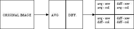
Generalizing it to two dimensions, we take the 1D Haar transform first along the rows, then along the columns of the image. If the width or height are not multiples of 4, then the borders are ignored in the transform.
We found this transform to be relatively ineffective in steganography. The Haar transform generalized to two dimensions allows more data to be stored in a regular image.
The 2D Haar Transform also works on a set of 4 pixels, but is considered "2D" because there is additional processing on a 2 x 2 block after the initial row and column transformations are completed. The transformation of a set of pixels:
![]() is
is ![]()
Again, borders for an image with width or height that are not multiples of four are ignored.
As in the 1D transform, the transformation is generalized to two dimensions, first along the rows, then along the columns. Additionally, after this computation is complete, we need to work on the upper left-hand corner (2 x 2 pixels) of each 4 x 4 block.
![]() becomes
becomes ![]() .
.
The same computation is done for the second row of pixels, and then again for each column of this 2 x 2 block.
The inverse is first computed for each group of 4 x 4 pixels. To do this, we take the
inverse for the first two columns in the 2 x 2 block, then take the inverse for the first
two rows in the 2 x 2 block. The inverse is: ![]() , for the E and F shown above.
, for the E and F shown above.
Finally, the inverse is taken for each group of 4 pixels; first by columns, then by
rows, as follows: ![]() , for the A, B, C, and D above.
, for the A, B, C, and D above.
These transforms were used in wavelet-based steganography. The amount of data that can be hidden in an image depends upon the number of "low" coefficients generated by the transform.
Generalized Lth Decomposed Haar Transform
For watermarking, the two-dimensional Haar transform discussed above was generalized for an arbitrary number of decompositions. Whereas the two-dimensional transform works on a 4 x 4 block of pixels, the Lth level decomposition works on a 2n x 2m image. Any odd pixels on the borders are ignored. For each pair of pixels, the average is stored in the first half of the row or column, and the difference is stored in the second half of the row or column. Again, we take the transform in two directions - first along each row, then along each column. After this step, we have stored all the averages in the upper left-hand quadrant of the image:
We can do the same decomposition on the upper left-hand quadrant up to L times, where L is log2(min (height,width)). The assumption here is that the most "important" pixels get stored in the top left quadrant of each level of decomposition, and the "details" are pushed into the other three quadrants.
Wavelet-based steganography is a new idea in the application of wavelets. However, the standard technique of storing in the least significant bits (LSB) of a pixel still applies. The only difference is that the information is stored in the wavelet coefficients of an image, instead of changing bits of the actual pixels. The idea is that storing in the least important coefficients of each 4 x 4 Haar transformed block will not perceptually degrade the image. While this thought process is inherent in most steganographic techniques, the difference here is that by storing information in the wavelet coefficients, the change in the intensities in images will be imperceptible. For this project, we only show the effectiveness of storing data in grayscale (.pgm) files.
The Haar transformation returns many coefficients that are 0, or close to 0. After taking a Haar transform of some image, the idea is to hide bits in the coefficients that are below some threshold value, then save the Haar inverse of the modified data. Theoretically, since we are hiding bits in insignificant coefficients, this should not greatly modify the image.
Encoding:
Decoding:
After analyzing both the 1D Haar transform and the 2D Haar transform, it was determined that the 2D Haar transform would be able to store more data. One or two bits of information can be stored for each Haar coefficient below a threshold value. This threshold value depends on the number of bits hidden in each coefficient. For example, when hiding 2 bits in each coefficient, we can hide in coefficients ranging from 0 to 3. When hiding 1 bit in each coefficient, we can hide in coefficients ranging from 0 to 1. Obviously, there is more degradation in the image when hiding in a greater number of bits, but the amount of data that can be stored is more than tripled. The degradation of an image storing in 2 bits is so slight that there is almost no advantage in storing in only 1 bit.
The main problem encountered in implementing this algorithm was the error caused by truncating the values of coefficients after a Haar transform. To hide bits, the floats introduced in the transform need to be truncated to integers (by rounding or by truncating). Taking the inverse Haar transform immediately after truncation results in errors caused by values greater than 255 or less than 0. The solution for this problem involves what we call the "range" and "bias" of an image. The range of an image limits the minimum and maximum values of the histogram. The application statically maps all values above 255-range to the value of 255-range. It also maps all values below range to the value of range when reading in the original image. After the data is hidden, this slight modification takes care of the values that fell above 255, but it didn't take into consideration the negative values that are introduced. This is where the bias comes in. The bias statically shifts each value by bias just before writing out the image. This shift does not introduce any values above 255 because of the range mapping that was done previously (as long as the range and bias are chosen intelligently).
Hiding the data was relatively straightforward. The first three bytes of the hidden data are part of the "magic number" -- the method used to determine if there is data hidden within the image. The fourth byte tells us the number of bits of the Haar coefficients in which the data is to be hidden. The fifth byte is the number of bytes of the length of the message (say n). Then the next n bytes determine the length of the message. So for any given data that needs to be hidden, there is at least six bytes of overhead. This header is always stored in the last two bits of relevant coefficients. In returning the number of bytes that can be stored by any given image, we always allow for 20 bytes of overhead, and check the number of bytes which need to be hidden before storing any data.
The actual data was hidden by systematically taking the first n bits of the data stream, and modifying the last n bits of the next Haar coefficient which falls within the given range. This continues until the data is completely hidden in the Haar coefficients of the image. Taking the inverse Haar transform, standard pixel values are returned, and written out in portable graymap (pgm) format.
The research aspects of steganography deal mainly with experimentation on where to hide the data and how much data can be successfully hidden without visual distortion. In our algorithm, we hid the data in the last bit or the last two bits of insignificant coefficients of the Haar wavelet transform. The amount of data that can actually be hidden in a regular image ranges from 6% to 7% of the size of the image. This is, of course, image specific, but the ranges are approximately correct for the images we tested. The sizes of the test images ranged from 120 x 120 to 1073 x 790, with various sizes in between. Again, steganography is not meant to be robust. Any modifications to the file - conversions between filetypes and standard image processing will remove the hidden bits from the file.
For each sample image, two sets of data were hidden:
In each case, the algorithm extracts the correct string and binary file if there was enough bytes in the image to store the entire string or file. The 876Kb image file (1073 x 790) could store just over 55Kb of information.
Improvements to the current design include:
Wavelet-based watermarking is more difficult than steganography because the watermark needs to be able to survive image processing. On the other hand, in watermarking, we can make the assumption that we have access to the original watermark and the original image. We proposed to use the Lth level Haar decomposition on both the original image and the watermarked image, and for each level, store the most important bits of the watermark into the most important bits of the image. In comparing the extracted watermark, we look at the number of bits in the most important part of the watermark (in the Lth level decomposition).
Watermarking:
Extracting:
The Lth level Haar transform was used for watermarking. The Lth level transform retains a global view of the image, while the 1D and 2D transforms implemented for steganography are localized to the 4 x 4 block.
We constrain the watermark to be at most 1/8 of the size of the image. The reason for this is to allow for repetition when hiding the bits in the watermark. We also constrain the watermark to be a power of two. This way, no pixel information is lost (since we ignore odd dimensions) when we take the Lth level decomposition. In watermarking, we store information in every coefficient of the Lth level decomposed image, but we only modify the last bit to minimize image degradation. After implementing steganography, we were aware of the inherent problems in modifying the data before taking the Haar inverse of the image. Again, we looked to range and bias to alleviate some of these problems. The range and bias in watermarking had to be slightly higher because taking the inverse of the Lth level decomposition propagated error throughout the entire image, so we had to be conscious about what reversing the decomposition was doing to the image.
Again, hiding the data was relatively straightforward. The watermarked image needs to be normalized for use. Creating a watermark involves reading in a base watermark, and outputting the same watermark (with padding if necessary to make it a power of 2) and introducing the range and bias into it. This watermark is decomposed L times to 1 pixel. Next we bias the watermark again, so it contains only positive integers. This is the information we hide in the image.
The original image is also decomposed L times, and truncated. A quadrant in the last level is at least 8 x 8 by our assumption that the watermark is at most 1/8 of the size of the image. The bits in the quadrants of each level of the watermark are hidden in the corresponding section of the original image. If we assume that the largest possible integer we need to represent in the decomposed, truncated, and biased watermark is 511, then we only need to hide at most 9 bits of information. This means that we can hide the data for each level at least 7 times, depending on the size of the image.
The actual data is hidden by systematically taking the first bit of the watermark level we are considering, and modifying the last bit of the next Haar coefficient. This is done for each level of the Haar decomposed watermark. Finally, we take the inverse Haar transform L times so that standard pixel values are returned, and can be written out in portable graymap (pgm) format.
Extracting the watermark requires decomposing a watermarked image, getting the data from the Lth level decomposition, and storing it properly as an Lth level decomposition of another image. The original watermark is needed for comparison. Because we are storing bits, a flipped bit could make visual identification of the watermark difficult. Instead, we compare the most important bits of the original watermark to the most important bits of the extracted watermark. We define "the most important bits" to be the upper left quadrant of an Lth level decomposed image.
The tests were performed on various images, using the same watermark2, scaled to 16 x 16, 32 x 32, 64 x 64, and 128 x 128. The JPEG images were compressed by 15 time their original size. Analysis of JPEG compression by up to 25 times the original, shows similar results. (For example, for the 32 x 32 watermark in the Renoir, the percentage of matching bits was 98.6%.)
Size of the watermark |
16 x 16 |
32 x 32 |
64 x 643 |
128 x 1284 |
|
No modification |
Renoir.pgm (1073 x 790) | 100 % | 100 % | 100 % | 100 % |
| F-18.pgm (640 x 480) | 100 % | 100 % | 100 % | 100 % | |
| flowers.pgm (640 x 480) | 100 % | 100 % | 100 % | 100 % | |
| Pitts.pgm (512 x 480) | 100 % | 100 % | 100 % | 99.9 % | |
JPEG |
Renoir.pgm | 97.9 % | 99.7 % | 98.8 % | 91.2 % |
| F-18.pgm | 86.1 % | 88.2 % | 85.8 % | 78.3 % | |
| flowers.pgm | 100 % | 98.4 % | 93.1 % | 77.1 % | |
| Pitts.pgm | 91.0 % | 93.1 % | 89.8 % | 79.4 % | |
Sharp |
Renoir.pgm | 93.8 % | 98.4 % | 98.7 % | 89.6 % |
| F-18.pgm | 93.8 % | 98.4 % | 99.3 % | 91.1 % | |
| flowers.pgm | 93.8 % | 98.4 % | 91.4 % | 74.0 % | |
| Pitts.pgm | 93.8 % | 98.4 % | 86.4 % | 52.2 % | |
Blur |
Renoir.pgm | 59.0 % | 62.8 % | 56.6 % | 53.5 % |
| F-18.pgm | 55.6 % | 56.8 % | 56.6 % | 58.1 % | |
| flowers.pgm | 64.6 % | 65.6 % | 55.9 % | 53.4 % | |
| Pitts.pgm | 58.3 % | 61.8 % | 59.9 % | 57.6 % | |
Crop |
Renoir.pgm | 54.9 % | 67.7 % | 50.8 % | 49.9 % |
| F-18.pgm | 55.6 % | 56.6 % | 53.2 % | 52.6 % | |
| flowers.pgm | 49.3 % | 51.9 % | 49.4 % | 50.1 % | |
| Pitts.pgm | 55.6 % | 51.4 % | 51.3 % | 50.8 % | |
The correlation for blurring and cropping is insignificant. The number of bits that correspond to the original watermark are most likely due to chance. However, the correlation in JPEG conversion (and reversion to portable graymap) and sharpening is not due to chance. JPEG, which retains the "important" information of the image, will be robust to this watermarking process. Because JPEG throws away "unimportant" information (thus, it is considered lossy), but retains what it considers "important" information, the watermark remains relatively intact. In fact, any image processing technique that retains, in the Haar sense, the "important" color information, will be robust to this algorithm.
The high level of correspondence also relates to the actual watermark image. The watermark must not be "dense" in any one-color sense. The Lth level decomposition of such a watermark will return many 0 (or close to 0) coefficients. Such a watermark is susceptible to changes in the watermarked image.
Because of the poor results in image processing which changes the overall intensities of the image, other watermarking techniques were applied with similar levels of success. We started by embedding a watermark that was not normalized and did not fit into any particular set of specifications. The results were more significant after we added the constraints mentioned above to the watermark. One technique we tried was to embed the decomposed watermark in only the positive coefficients of the decomposed image. Another technique was to embed the unchanged watermark into the Lth level decomposed image, and the resulting image processed. In each case, even slight processing to the image, which modifies the intensity of the image destroys the watermark.
Improvements to the current design include:
The number of applications of wavelets continues to increase. Steganography and watermarking are just a few of those applications. Steganography in the wavelet domain looks very promising. The perceptual differences of images trivially modified in the Haar wavelet coefficients are almost nonexistent. The amount of data that can be hidden is potentially up to a quarter of the size of the original image, depending on the image. The algorithm we implemented in watermarking is not very robust to intense image processing, but it works quite well for graphic conversions, where the overall image information remains the same. In addition, the watermark is not perceptually visible. With some modifications, the ideas presented in this paper are encouraging to future work in wavelet based watermarking. There are many things to consider for future enhancements and research in both wavelet-based steganography and wavelet based watermarking.
1: Nicolaou, Alex. "A Wavelet Wading Pool" August, 1996. http://www.cgl.uwaterloo.ca/~anicolao/wadingpool/WaveletWadingPool.html
2: The watermark was created as 32 x 32, and scaled to various sizes.
3: F-18.pgm, flowers.pgm, and Pitts.pgm are not at least 8 times larger than the watermark in one direction
4: Renoir.pgm is not at least 8 times larger than the watermark in one direction. The other images are not at least 8 times larger than the watermark in either direction.
Cox, Ingemar J., Joe Kilian, Tom Leighton, Talal Shamoon. Secure Spread Spectrum Watermarking for Multimedia. IEEE Transactions on Image Processing, 6, 12, 1673-1687, 1997.
Johnson, Neil F., Sushil Jajodia. Exploring Steganography: Seeing the Unseen. IEEE Computer, 26-34, 1998.
Morimoto, Norishige, Walter Bender, Daniel Gruhl Techniques for data hiding MIT, Media Laboratory.
Appendix A - Steganography Results
Here we show one example the wavelet-based steganography technique. The hidden data was a scaled-down JPEG image of the original file of dimension 320 x 200.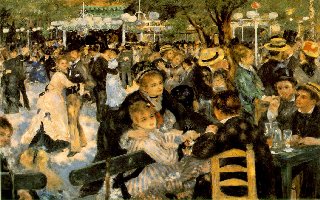

Appendix B - Watermarking Results
Four watermarks were embedded into the same image as above (original image), the same image was used for the watermark, scaled to 16 x 16, 32 x 32, 64 x 64, and 128 x 128.![]()