CS4620 PA5 Splines
Out: Monday 2 November 2015
Due: Friday 13th November 2015 (11:59pm)
Project 5 Splines
Do this project in groups of two. You can use Piazza to help pair yourselves up.
Do the written part alone.
Introduction
On past assignments we have created straight lines and spheres. However, the question remains: how are we supposed to model chess pieces? Or vases? Curvy letters such as "s" in typography? The answer: splines! In the most general sense, splines are piecewise polynomial functions that specify potentially complex curves mathematically. In this assignment, you'll get a chance to play around with some splines, and ultimately create some really neat objects to add to your scenes.
In this assignment, you will explore representing a Catmull-Rom Spline curve with several cubic Bézier by completing some warm-up exercises, implementing De Casteljau's algorithm, and rotating an arbitrary 2D spline in 3D space to create a surface of revolution. Again, we will provide framework code, so your focus is on implementing the more "interesting," graphics-related components. However, you also have some freedom to redesign our system as you see fit.
Programming Exercises
Getting Started
A new commit has been pushed to the class Github page in the master branch. We recommend switching to your master branch, pulling this commit, and creating a new branch (e.g. A5-solution) and committing your work there. This new commit contains all the framework changes and additions necessary for this project EXCEPT FOR THE CODE FROM A3. For this project to work correctly, please remember to copy over your solution from A3.Specification and Implementation
We have marked all the functions or parts of the functions you need to complete with TODO A5 in the source code. To see all these TODOs in Eclipse, select Search menu, then File Search and type TODO A5. There aren't too many of these because we've made all the programming you need to do happen in just three files. The files are
- SplineCurve.java
- CatmullRom.java
- CubicBezier.java
See the face?
This assignment is best broken down into the following parts. We highly recommend completing the parts in order:
- Tessellation of Bézier cubic functions
- Composition of Bézier cubic segements to form a Catmull-Rom Spline
- The code to generate a surface of rotation (similar to the mesh assignment)
We've provided you with some basic functionality. The short version: we provide the UI to edit the control points of your spline and to draw the surface of revolution.
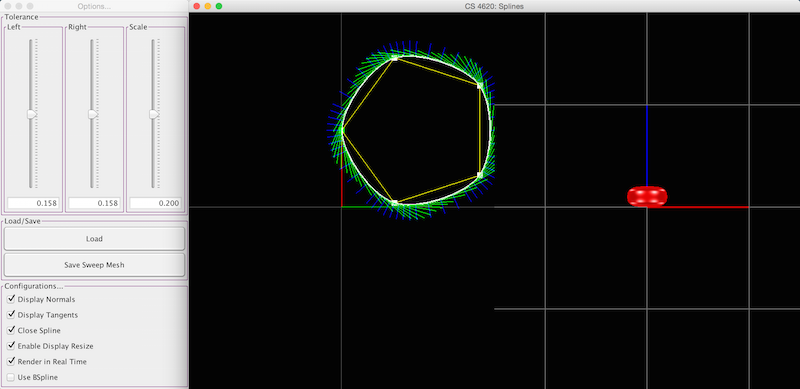
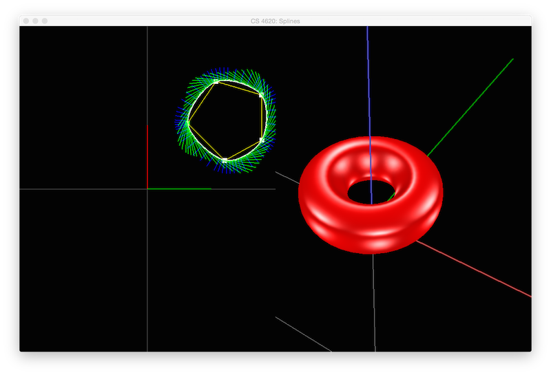
The long version: In the interface, there are two visual panels and a control window. The left visual panel edits the spline before revolution. This panel also displays normal vectors (blue) and tangent vectors (green). The right panel displays your resulting surface of revolution. Triangles that face you (i.e. you see the points specified in a CCW order) are red, whereas triangles that don't face you (i.e. you see the points specified in a CW order) are gray. The controls are very similar to the scene assignment's controls. In the control window, you are given additional functionality, including saving/loading and some display options. (Surfaces of revolution are saved as OBJ files that are annotated with the spline data; this means you can only load OBJ files that were saved with this application.)
Dealing with splines is a bit tricky in terms of inside-outness. For instance, if I specify a circular spline, who's to say whether or not the normals are facing inward or outward? For this assignment, we will adopt the common convention -- a closed spline that makes a single CCW loop has the enclosed region of the plane on the inside, and the rest on the outside. Its normals point away from the center of the loop. On the other hand, a CW loop has the enclosed region on the "outside". In both cases, as you walk along the curve, the normals point to your right. Similarly, for open splines, the tangents should align with the direction of parametric increase, with the normals pointing to the right.
Tesselation and De Casteljau
Your first job is to fill in your Bézier curve, given your newly properly converted control points. The motivation for converting the segments to Bézier form is the availability of a simple method for splitting Bézier segments in two. Using de Casteljau's algorithm, one can compute the set of points shown here, given starting points. This image uses u=.5, but the method supports u in the normal range, [0,1].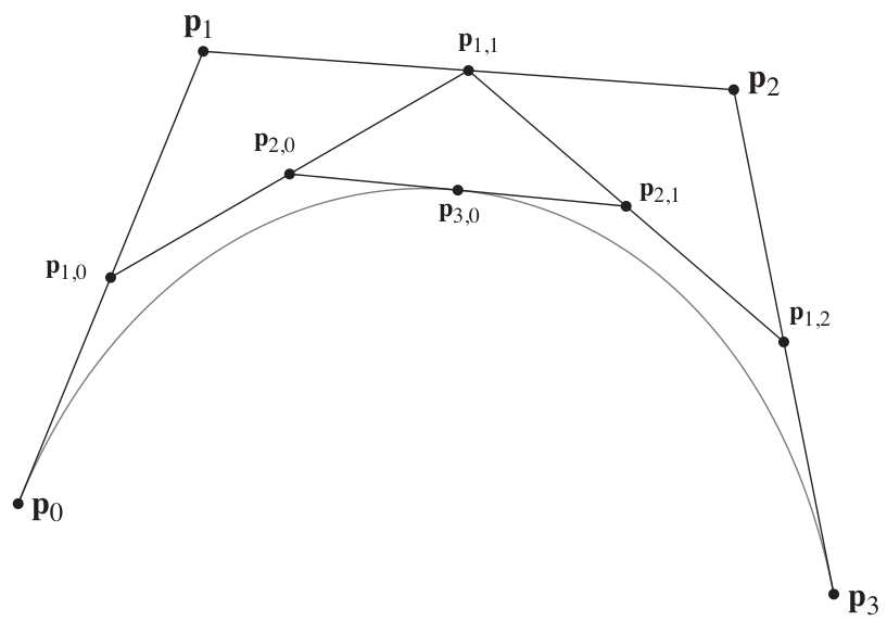
The pattern here is a simple recurrence in which points at each level are linear combinations of points at the previous level: p{k,i} = (1 - u)p{k-1,i} + u p{k-1,i+1} p{0,i} = pi, where the pi with a single index are the control points.
This construction not only gives you a point on the spline for a given u; it also gives you the Bézier control points of the two halves, which can also be thought of as cubic Béziers: they are p0, p{1,0}, p{2,0}, and p{3,0} for the left half and p{3,0}, p{2,1}, p{1,2}, and p3 for the right half.
The simplest way to get the spline on the screen is to use this recurrence to compute f(u) (which is the point p{3,0} for a sequence of regularly spaced u values. We encourage you to implement this first, to make sure you have the algorithm right.
A better way, which you should implement for your final handin, is to recursively split the segment, terminating when the control polygon is straight enough. The idea is as follows: consider an additional parameter epsilon that specifies curve smoothness. Specifically, to approximate a Bézier segment with lines, you can use a single segment if the angles between the edges of your control polygon are both less than half the angle tolerance (given by epsilon) because the tangent to the curve cannot swing more than that much over the segment. If the angles are too big, subdivide and apply the idea recursively.
Put another way, you should subdivide the curve below if either θ{0,1,2} or θ{1,2,3} is larger than half of the input epsilon parameter.
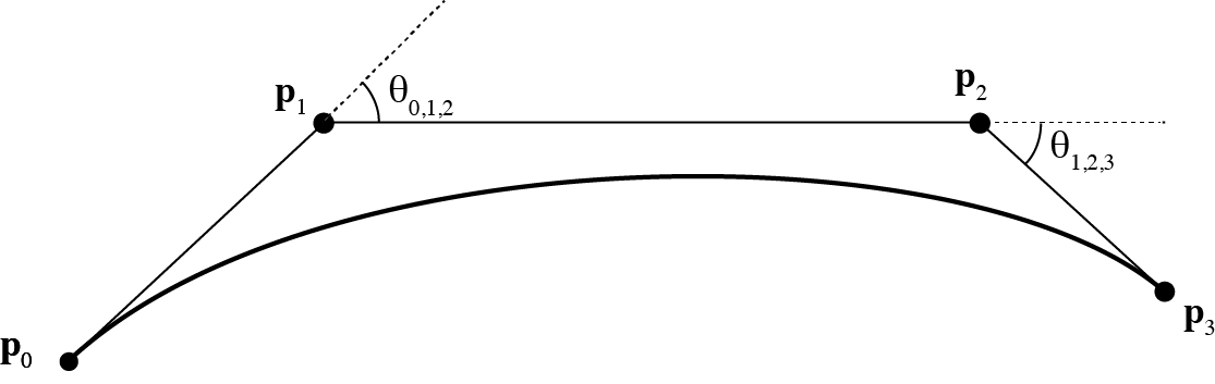
The angles in the two halves will be smaller (less sharp) after subdivision so ultimately the recursion will terminate for well-behaved curves. You should also enforce a maximum on the number of levels of recursion (10 is a good choice) to prevent stack overflow in degenerate cases. Also, your recursive algorithm should only emit points that are exactly on the spline (so don't add other points you may have computed that aren't on the curve).
The function you need to implement, tesselate(), has three jobs -- it needs to set this.curvePoints, this.curveNormals, and this.curveTangents correctly. As such, you should come up with a way to calculate the tangents to the spline for each point computed by your recursive algorithm. There are a few easy ways to do this, just pick one that is correct and makes sense to you, and explain it briefly in a code comment. From these tangents, compute 2D normal vectors that are perpendicular to the curve.
Your cubic Bézier code should work independently of all other code -- we highly recommend adding a main() into this class for testing and debugging purposes.
From Catmull-Rom to Béziers: Setting Up Your Béziers
To draw our Catmull-Rom splines, we'll first convert them to cubic Bézier curves. Your job is to implement this conversion in the toBezier() method in CatmullRom.java, and the setBeziers() method in SplineCurve.java.
The toBezier() method in CatmullRom.java simply uses the control points of a single Catmull-Rom segment to create an equivalent Bézier curve. This should be as simple as constructing the relevant matrices and multiplying the control points.
The setBeziers() method in SplineCurve.java constructs an ArrayList of Béziers, bezierCurves, that make up the SplineCurve (the parent class of CatmullRom). The spline editor hands you a list of control points, numbered from 0 to N-1, which are provided in the ArrayList controlPoints. These control points define a chain of curves that we'll want to draw. Finding which four control points influence a segment of the Catmull-Rom Spline is mostly simple: segment i of the curve is influenced by control points i-1, i, i+1, and i+2. Using this definition we can generate N-3 Bézier segments from the N control points without falling off the ends of the sequence, which is exactly what we'd like to do in the case of an open curve. However, you may have noticed a boolean called isClosed in your SplineCurve. To handle closed splines, you'll need to tack on a few additional Bézier curves. We'll let you figure out exactly how to handle this, but know that you'll need to "wrap around" to the start of your control point list.
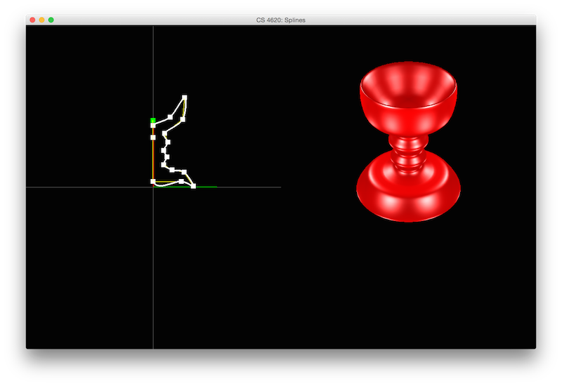
The Grand Finale, Surfaces of Revolution
Here, you will revolve your cross sectional SplineCurve around the z-axis to make a triangle mesh surface of revolution. The procedure is very similar to the Mesh assignment: we'll we want to generate the positions of vertices, indices, and normals for our surface and fill data buffers with the result. This code will go in the build3DRevolution() method of SpineCurve.java.
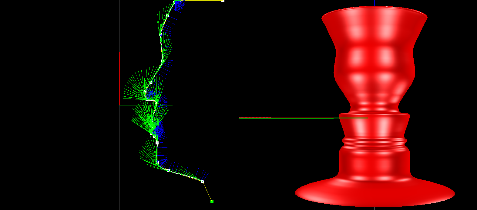
Each tessellation vertex along our input spline (which can be retrieved by using SplineCurve.getPoints()) will define a circular cross section of our surface parallel to the XY-plane. Similar to the tessellate() method, we will use a tolerance value to determine how coarse each cross section circle will be. The sliceTolerance argument specifies the maximum angle between consecutive vertices within these circles.
You will need to rotate the input 2D vertices (which lie in the XY-plane) such that the surface revolves around the Z-axis. Simultaneously, you will need to use the scale argument to scale the surface of revolution.
As a convention, your mesh should be oriented so that when the cross sectional spline has outward-pointing normals and is within the positive X half space, the triangles should be oriented in counter-clockwise order (i.e., the surface should appear as red with Blinn-Phong highlights).
Extra Credit: B-Splines
Catmull-Rom splines are only one type of cubic spline curve; there's no reason that another type of cubic spline can't be used in this framework. B-Splines are similar to Catmull-Rom splines, though they do not necessarily pass through their control points. For extra credit, you can implement the toBezier() method of BSpline.java; its purpose is the same as the method in CatmullRom. Once you've implemented this, you should be able to check the 'use BSpline' button on the left panel.
What to Turn In
- Your written solutions
- Your(zipped) src folder
- An image of an interesting surface of revolution that you create!