ECE/CS 314: Computer Organization Fall 2004

Project 3: Logic Design
Due: November 8, 2004


  Special Setup Instructions
 

In order to make includes work properly in your CAST files on the BSDCluster machines, you need to set the environment variable CAST_HOME:

setenv CAST_HOME /usr/local/cad
This command must be run every time you log on. As usual, you can put this in your .cshrc file if you wish.
 
Basics
 

All ECE/CS 314 projects, including this one, are done in groups of exactly two students. Please link up with a partner and submit a single solution. If you do not have a partner yet and cannot find one, use the course newsgroup to find one.

Please read this document completely before starting.

  • The template files for this project are on the BSDCluster in /usr/class/ececs314/proj3.tar.gz. You can extract them into your current directory by executing
    tar xzfv /usr/class/ececs314/proj3.tar.gz
    This creates a directory named ececs314/proj3 that contains the template files for this project.
  • You will turn in this project electronically. See the end of this document for specific details.
  • The project will be graded out of 100 points.
  • The consultants can help you when you encounter problems. The consulting schedule is posted on the course web page. If you still have problems after talking to the consultants, you can try the course newsgroup, e-mail your questions to one of the TAs, or schedule an appointment.
  • It is a good idea to do the paper designs of you hareware before you implement them in CAST.
  Project Goal
 

This project has several goals: to become familiar with the logic design and testing environment by designing simple logic blocks; to design a more sophisticated finite-state machine with the logic design tools, and finally to implement an ALU suitable for your MIPS processor project, using the techniques described in recent lectures. To successfully complete this project, you will need to understand the following items:

  • Logic design
  • Finite state machines
  • ALU Design
  • The logic design and simulation tools
  Part 1: Logic Design
 

The aim of this part of the project is to design simple logic blocks and become familiar with the logic design tools we will be using for the class.

Combinational Logic. Write down the truth table and logic equations for a combinational circuit that takes a 4-bit input, an integer in sign-magnitude representation, and produces a 4-bit output that is the same integer in 2's complement representation. Write a CAST file implementing the combinational logic (well, just edit  sign2two.cast), and simulate your design using irsim .  Use the test_sign2two.cast as the file that creates the instance of sign2two.

Create an irsim source file called test_sign2two.cmd that contains all the tests you performed on your circuit. Use irsim to measure the worst-case delay through the combinational circuit for each output bit (report this number in your README file). Attempt to minimize this delay by optimizing your combinational logic using Karnaugh maps, and by using NAND/NOR gates instead of AND/OR gates.

Examples of writing CAST programs and simulating them with irsim can be found here, and some commonly used irsim commands are here .

The 314/parts.cast that is imported contains definitions for Nand2 (2-input NAND), Nor2 (2-input NOR) and Inv (inverter). You might want to define your own collection of parts (put them in file myparts.cast) that you reuse for the different parts of this project. More information on the 314/parts.cast file can be found here .

Building-Blocks. Define a CAST cell called BusMux32 that defines a 2-to-1 MUX with a one-bit select line, two 32-bit buses as inputs, and a 32-bit output bus. Put your definition in myparts.cast. Buses are defined in the 314/parts.cast file that is imported at the top of your file. The definition is:

define Bus(int N) (node[N] d) { }
Therefore, the statement
Bus(32) b;

creates a 32-bit bus. Buses can be used as parameters to definitions, just as nodes can. Given the declaration shown above, we can access the different data signals in the bus b as b.d[0], b.d[1], etc., upto b.d[31].

  Part 2: A State Machine for the Game of Life
 

The goal of this part of the project is to design the state machine for a single cell in "The Game of Life" and then to connect these cells together into a 4x4 "toroidal" grid. There's a really good description of the game along with a neat applet for exploring the details of the game online at http://www.math.com/students/wonders/life/life.html. The key rules of the game are:

  • A dead cell with exactly three living neighbors becomes alive (birth)
  • A living cell with two or three neighbors stays alive (survival)
  • In all other cases, a cell dies or remains dead (overcrowding or loneliness)

Your single cell has the following function header:

define LifeCell()(node[8] in; node init; node out){ ... }

The node[8] in array represents the status of each of your neighbors (N,NW,W,SW,S,SE,E,NE): logic 1 means a neighbor is alive, logic 0 means a neighbor is dead. A cell's output node should be high if the cell is alive and low if the cell is dead. The init input should be used to determine the state a cell initializes to when the (global) Reset signal is high. If init is zero the cell should be initialized in a dead state, otherwise it should be initialized in a living state. You must implement a life cell as a Moore-style State Machine! Define your cell in lifecell.cast (the function header is provided in this file). You should instantiate and test a single LifeCell to make sure it behaves correctly according to the rules of the Game of Life.

Once you're satisfied with that your cell is working correctly in isolation you need to connect up a 4x4 "torroidal" grid of LifeCells. This just means it's adjacency properties are like those of a K-map (e.g. the top row is "adjacent" to the bottom row, the leftmost column is "adjacent" to the rightmost column, and consequently all corners are "adjacent"...). The definition of the grid is as follows:

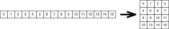
define LifeGrid()(node[16] init; node[16] out){...}

The node[16] init vector specifies the initial state of the grid, and the node[16] out vector should reflect the state of the grid at any given time. When RESET is high the LifeCell corresponding to the i-th grid cell should take on the value designated by init[i]. The vectors map onto the grid in a "row major" format as shown in the following diagram:

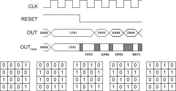
Each generation should be computed in a single clock cycle. That is to say, after the RESET period the state of the grid will be well defined and thus the inputs to all state machines will be stable. Some amount of time (less than a clock cycle) later all cells should compute whether they should live or die in the next generation. At the next positive edge, the state of all cells will change concurrently. Subsequent generations should proceed similarly. Note that the inputs to all state machines will change with the state (slightly later, actually).

You will need to understand the use of the global signals CLK and RESET in order to do this part of the project. Use only positive edge-triggered flip-flops for state-holding elements. Define the LifeGrid in the provided file lifegrid.cast (the function header is in this file).

Remember that this is a Moore machine and Reset is an input.  If Reset changes during a cycle, it's effect takes place in the next cycle.  If the output of your state machine changes within the same cycle as a change to Reset occurs, it isn't a Moore Machine and will lose a lot of points.

  Part 3: The MIPS ALU
 

Our ultimate goal is to design a complete pipelined MIPS processor. The goal of this part is to complete the logic design of an ALU, with emphasis on correctness rather than performance (for now).

You are to design an ALU (skeleton provided in alu.cast) that takes three inputs and produces one output. The three inputs are:

  • Bus(32) a, b; /* two input buses */
  • ALUctrl c; /* an alu control input */
The output of your ALU is
  • Bus(32) out; /* one output bus */
This output value depends on one or both of the values on the input buses as well as on the operation specified by the ALU control input c .

ALUctrl is defined in $CAST_HOME/cast/314/mips.cast. Make sure you understand this definition completely. The ALU control picks the operation that is to be performed by the ALU. The ALU operations to be implemented are: add, and, xor, or, nor, sub, sltu, slt, sra, srl, and sll. The operation to be performed is selected by the appropriate ALU control signal being a 1 (you may assume that at most one of these control signals will be 1). For each of these operations, the output is defined as follows (using a C-like syntax):

Operation Output
add out = a + b
and out = a & b
xor out = a ^ b
or out = a | b
nor out = ~(a | b)
sub out = a - b
sltu out = (a < b) ? 1 : 0 (unsigned compare)
slt out = (a < b) ? 1 : 0 (signed compare)
sra out = (b >> c.sa) (signed right shift)
srl out = (b >> c.sa) (unsigned right shift)
sll out = (b << c.sa)

(out is 32-bits, so assigning 0 to out assigns 0 to each bit; assigning 1 to out assigns 1 to out.d[0], and 0 to every other bit of out .)

Place the documentation for your ALU in the README file. The documentation should describe the implementation strategy for your ALU. You may place the ALU documentation in comments in your alu.cast file (the README should contain a pointer to the documentation in either case). The README file must contain the worst-case delay through your ALU.

Testing. We've provided a test file called testalu.cast that imports your definition and creates a circuit containing one ALU. Run prs2sim on this file to create .sim and .al files for your ALU that can be run through irsim .

You must submit an irsim script file testalu.cmd that can contains all your ALU tests. These tests must be documented in the README. The following are some suggestions for testing your ALU thoroughly. Make sure your test cases for logical operations produce both a 0 and a 1 on each output bit. You should test both positive, negative, and zero numbers for shift right, and several interesting numbers for add, subtract, and slt/sltu. The irsim script file must demonstrate each operation working.

Hints.

  • The ALU is a purely combinational circuit.
  • Design a bit-slice of the ALU and then create an array of these appropriately connected. This strategy works well for everything except a carry-lookahead adder or an efficient shifter.
  • You might want to steal some of the parts we described in Lecture, possibly “re-engineering” them a bit to reduce delay.
  • You may use GND for logic 0, and Vdd for logic 1. These are global signals defined in 314/parts.cast.
  • Document each major definition used by your ALU, and show how they are combined to construct the complete 32-bit ALU. “Standard” cells like And2, Or2, And3, Or3, etc. need not be documented.
  • For the worst-case delay: think about which case would have the largest number of sequential steps from input to output.
  • Note which register gets shifted.
  • For set instructions, you have to set the whole word, not just the last bit.
  Submitting Your Project
 

Submission will be done using CMS.  No written report will be required for this project except for a README file which must contain the following:

  • The first four lines MUST BE:
    NAME: username1 username2
    Name of person1
    Name of person2
    PROJECT 3
    where username1 and username2 are the login ids of you and your partner.
  • Worst-case delays computed by irsim for your sm22c circuit of Part 1.
  • Documentation of your game-of-life cell testing strategy.
  • Worst-case delay for your ALU computed by irsim.
  • Documentation and testing strategy for your ALU.
  • Any special information you'd like us to have regarding Parts 2 and 3.

For this project, you will edit:

myparts.cast, sign2two.cast, lifecell.cast, lifegrid.cast, alu.cast

You will add a README and .cmd files for testing.  You shouldn't need to change the test_ files, they just create an instance of the hardware which you will test.

 There is a script available that will tar these up for you, and check that all the files are present, so that you can submit them to CMS.  Once you have finish the project, simply type:

proj3tar.314

from your proj3 directory. This will create the file proj3_valid_sub.tar.gz, a compressed archive of all the files in your project. Upload this file to CMS, following the instructions in the CMS documentation.