
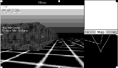
Figure 1: The CU-SeeMe VR User Interface
Jefferson Han, Brian Smith
Department of Computer Science
Cornell University
Ithaca, NY 14853
{jyh4,bsmith}@cornell.edu
Current video-conferencing systems provide a video-in-a-window user interface. This paper presents a distributed video-conferencing system called CU-SeeMe VR that embeds live video and audio conferencing in a virtual space. This paper describes a prototype implementation of CU-SeeMe VR, including the user interface, system architecture, and a detailed look at the enabling technologies. Future directions and the implications of the virtual reality metaphor are discussed.
video-conferencing, virtual reality, cyberspace, ray-casting, spatial audio, segmentation
CU-SeeMe VR merges the CU-SeeMe video teleconferencing application [2] with a fast 3D graphics engine to create an immersive 3D chat environment. Live video feeds from conference participants are projected onto 3D walls that roam around in a virtual conference room. The user freely navigate around the 3D world. The interface draws on user intuition: the interaction metaphors in a physical conference room carry over to the virtual world. If you want to talk to someone, you walk up to them. If someone is offensive or boring, you can move away. And as in reality, they can follow you around. This conference room is virtual- two people next to each other in virtual space could be thousands of miles away in reality.
Figure 1 shows the CU-SeeMe VR user interface. The interface consists of 7 regions: the 3D view window, the chat dialogue, the map view window, the navigation panel, the local video window, the audio control window, and the visibility control. The local video window shows the output of the local camera. The audio control window shows the level of the microphone and speaker volume.
These controls, which are standard on most video conferencing systems, are used to tune the parameters of the audio/video capture modules. The chat dialogue is used to transmit textual information. The visibility control sets a threshold for the video segmentation algorithm, described later.
The 3D view, map view, and navigation panel are at the heart of CU-SeeMe VR. The 3D view shows a projection of the 3D world from the user's perspective. The engine used to generate this view is described below. The map view window shows a schematic, bird's-eye view of the 3D world. It helps the user to understand his position in, and navigate through, the virtual world. Finally, the navigation panel allows the user to move around in the 3D world. Holding a mouse button down on the upper arrow moves forward, on the lower arrow moves backwards, on the left arrow turns the user's view to the left, and on the right arrow turns the user's view to the right. Keyboard accelerators are also provided for these functions. The map and 3D view are updated in real-time to reflect the changed positions.
This interface provides users with a 3D presence in, and ability to navigate through, a virtual world. Other users in the world are shown as flat planes texture-mapped with that user's video stream. As other users move through the virtual world, the position of their plane is changed. Simultaneously, the texture map is updated with incoming video data. These two mechanisms give the effect of a user walking (maybe more like sliding) through the virtual space. Though primitive, the mechanism works rather well. It works even better when foreground segmentation (discussed later in the paper) is used to cut out the user's head from the quadrilateral (you can see a segmented user on the right side of the 3D view, about the middle of the window).
In addition to providing 3D graphics, the user interface also spatializes the audio streams of the participants. People closer to you in the virtual world are louder than those far away, left and right stereo channels reflect the speaker's relative azimuth (left or right), and a speaker's voice gets louder when they face you.
The system is backwards compatible with vanilla CU-SeeMe. Regular CU-SeeMe clients are immobile, so we map them onto a fixed, rotating multi-faceted cylinder in the environment. Regular CU-SeeMe permits the participation of users without video (lurkers) that communicate through audio and text. For these users, we use a default bitmap as a texture map. We also use this bitmap for a normal video client's backside. Without this mechanism, it is hard to figure out which side of a client you are seeing from a distance.
The rest of this paper describes the design and implementation of CU-SeeMe VR. We first briefly review related work (section 2) and CU-SeeMe, the video-conferencing software on which our prototype is based (section 3). We then describe the system architecture, key algorithms, and performance of the system are described (section 4), Finally, we discuss limitations, applications, and implications of both the technology and the virtual reality metaphor (section 5).
CU-SeeMe VR combines elements of both computer graphics and video-conferencing. Both these subjects have a long and rich history.
The MBONE suite of video conferencing tools (vic, vat, nv) are among the most well-known [5][9]. Hewitt [4] provides an exhaustive review of current video conferencing products and standards. These tools provide video in a window as the primary mode of interaction. They are patterned after broadcast or telephone technology: users rendezvous by listening to a broadcast or calling each other explicitly. Fish, Kraut, and Chalfonte have experimented with a video wall installed in two parts of the same laboratory [8] to provide an environment more conducive to informal interactions than other tools. CU-SeeMe VR also provides an environment that encourages informal, chance meetings.
The Virtual Reality Modeling Language (VRML) is an Internet specification for 3D environments [3]. Models can be downloaded and viewed interactively using VRML browsers. Black Sun Interactive [7] is among the companies that has used VRML as a basis for an interactive environment similar to CU-SeeMe VR. These product include support for audio, but conference participants are represented by cartoon characters called avatars, which leads to fairly unrealistic and awkward interactions (e.g., a user presses F3 to smile). Many vendors believe that such products will become more widespread in the near future as operating system vendors include support for 3D graphics. Examples of such support is OpenGL, QuickDraw 3D, and Direct3D. Third party vendors are expected to include hardware support for these primitives in the near future.
More advanced research has explored the integration of video-conferencing into CAVE virtual reality environments [12]. Such environment allow geographically remote scientists to explore a virtual space together. The usage of such environments is limited by the equipment required (high end graphics workstations and an expensive, dedicated VR facility). Recent work on interactive building walk-throughs [6] shows that for real-time rendering of very complex spaces (millions of polygons) is possible.
This section briefly reviews the architecture of CU-SeeMe, the video conferencing engine on which CU-SeeMe VR is based.
CU-SeeMe is a desktop video-conferencing system developed at Cornell University that was designed to accommodate multiparty conferences over the Internet on low-cost personal computers [2]. It is available for both Macintosh and Windows, and is designed to run on as many computers as possible to allow for as much interaction as possible. Because CU-SeeMe can run on low-end PC machines with minimal network connectivity, it has enjoyed extremely widespread usage. Its audio/video transport engine at the heart of CU-SeeMe VR. Although our current implementation uses CU-SeeMe, the ideas in this paper can be applied to other video conferencing systems as well.
CU-SeeMe clients can be connected in a point-to-point fashion or through a central reflector. The reflector multiplexes multiple video streams over a single connection and gives the conference a star topology. For multiparty conferences, connecting to a reflector reduces the number of independent connections from n2 to 2n, where n is the number of clients in the conference. Over the years, the reflector has grown to include other operations, such as unwanted data pruning, bandwidth management, and transcoding. The reflector model also imposes limitations on the scaleability of the system. These limitations are discussion in section 5.
The reflector serves another purpose: it promotes social interaction by providing a common place to which users may connect. Users rendezvous at well-known reflector sites to meet other people. This support for casual interaction has made the program very popular.
CU-SeeMe's transport mechanism is a best-effort protocol built on top of UDP. It includes a robust auxiliary transport mechanism that allows data types other than audio and video (e.g. text) to be used in a conference. The protocol provides two modes of operation for auxiliary data: best-effort streaming and reliable transport. In CU-SeeMe VR, position data is sent over this auxiliary data stream using best-effort transport.
The CU-SeeMe codec utilizes lossless intra-frame compression on 8x8 pixel blocks of 4-bit, 160x120 gray-scale video. It also uses conditional replenishment: only blocks that have changed beyond a specified threshold value are sent as part of a frame update. Standard codecs (e.g., Intel DVI) are utilized for 8 bit, 8kHz-sampled audio.
This section describes the implementation of the CU-SeeMe VR system. Our architecture has three parts, the reflector, whose role was discussed above, the sender, which captures, compresses, and sends audio, video, and auxiliary data to the reflector, and the receiver, which decodes and displays audio, video, and auxiliary data from the reflector. We use an unmodified reflector. Our sender uses the capture, compression, and transport protocols of CU-SeeMe. The only modification we made to the sender was to add an auxiliary data stream containing the user's position in the virtual space. This design allows unmodified CU-SeeMe clients to receive and decode data sent by a CU-SeeMe VR application, since they ignore the auxiliary data stream.
The receiver's software architecture is more complex, and is shown in figure 2. The receiver splits the video stream into audio, video, and 3D position streams (other auxiliary data, such as textual chat data, is not shown). 3D position data consists of two triples. One triple specifies the user's position (x, y, z), and the other thriple specifies a normal vector (nx, ny, nz) that gives the direction the user is facing. These triples are recorded in a table, indexed by user id. Video data is decoded by the CU-SeeMe video codec and saved in a video buffer. A separate video buffer is maintained for each user. The 3D graphics engine combines the decoded video data with the model of the virtual world and the 3D position of each user to render the image on the user's display. To the codec, the video buffers are target images. To the graphics engine, they are texture maps. The graphics engine is discussed below.

The audio decoding pipeline is analogous. The audio decoder places decompressed audio data into an audio buffer, one per user. The audio mixer and spatializer uses the user position information to attenuate and mix the audio data to create a single audio output stream that is sent to the speaker. The spatializing and mixing algorithms are discussed below.
The 3D graphics engine renders the virtual world on the user's display. Although full-scale VR is still not practical on today's machines, we can provide a reasonable approximation using a technique called ray-casting. Since ray-casting is described in detail elsewhere [1], we will only sketch the algorithm here.
Ray-casting is a technique for extremely fast rendering of so-called first-person 3D scenes. First-person scenes are mostly-static environments viewed through a single camera that is free to move about in 3-space, but cannot pitch or roll. This constraint is acceptable because people generally can not fly and rarely tilt their heads. Ray casting places additional constraints on the environment: polygons (walls) in the scene must be orthogonal to the floor and non-intersecting. Despite these restrictions, such environments can appear rather realistic by suitable use of texture maps on the walls. The popular PC video game Doom, for example, uses ray-casting techniques. A sample image generated by our ray-casting engine is shown in figure 3.
Ray-casting is based on the principle of forward-ray-tracing, where the visibility of each pixel in the rendered image is determined by intersecting a view ray with the primitives of the environment. However, instead of computing this intersection for every pixel in the image, which is very expensive, it is computed only once for every vertical column of pixels. This is sufficient because the environment is constrained to have only vertical, non-intersecting walls.
The intersection list is then sorted by depth, and the vertical span in screen space representing each wall is computed using the traditional perspective-divide transformation. Rasterization proceeds in reverse depth order (from back to front), so that nearer walls are drawn over and occlude farther walls. This approach is called the Painter's Algorithm [10] and is sub-optimal. Two better ways would be to render front to back, keeping track of spans that have been written and masking those sections out, or to use a pre-computed data structure such as BSP trees [11].
Because all walls are orthogonal to the ground plane, and the viewer has zero pitch, every pixel in a vertical span has the same distance from the viewpoint. Thus, there is no need for a time-consuming perspective divide per
pixel -- one divide suffices for the entire vertical span. Each span is then rendered with a texture map into the frame buffer. The rasterization of the texture-map is also extremely fast because the portion of the texture copied to the screen is a simple scaling of the texture image. Floors (planes which are parallel to the ground plane) take advantage of similar optimizations. A user's video is integrated into scene by texture mapping it onto a plane whose position is determined from the 3D table information.
Sound directionality provides a strong cue for localizing sources of sound, or in this case, the voices of participants in cyberspace, especially when multiple sources are active at the same time. Thus, our conferencing engine includes and audio spatializer.
A complete solution to the spatial audio problem uses real-time convolutions to simulate the diffractive effects of the environment and the pinnae of our ears [13]. Implementations utilizing this approach require dedicated hardware for real-time performance and are not suitable for our application. We therefore explored the use of other cues to spatialize audio. We experimented with amplitude and phase differentials (i.e., differing volumes and arrival times of a sound to each ear), atmospheric/distance attenuation, and voice directionality.
In our first experiment, we modified the relative phase of the left and right audio channels to simulate the phase differential of a sound arriving to each ear. This phase differential is obtained by calculating the arrival times as a function of the angle of the sound source from the forward-facing direction, the source distance, and the inter-ear distance. We found that this cue is not significant, unless the phase distance is exaggerated so greatly that the sound is perceived as two distinct sounds, which is then interpreted as an echo.
Similarly, we tried incorporating the inverse-square attenuation due to the differing distance between a sound source and each ear, which creates a small amplitude differential. Again, we found this model gave no perceptible cue, since most of the amplitude differential is overwhelmed by the cross-talk between the left and right channels of the speakers.
We found that the best way to make a sound appear to come from the left, using external speakers, is to simply play it through only the left speaker. We proceed to pan a sound from left to right by increasing the right channel volume and decreasing the left using a sinusoidal function of the sounds angle from the forward facing direction. This function is then composited with a distance attenuation factor to achieve the final effect. The following formulas give the attenuation of the left and right channels.
where q is the angle between the direction the receiver is facing and the sound source, and d is the distance between the source and receiver.
Our final consideration is transmitter directionality. People often direct their voice at a specific person or audience, since their voice is louder in that direction. To simulate this effect, the receiver attenuates audio as a function of the angle between the source's normal vector and the vector between the source and destination. We have found that a cardioid function of this angle works well:
where a is the minimum amplitude received (from directly behind). Figure 4 graphs this function.


These techniques provide source attenuation, but do not create a convincing environment. A more complete solution would include other effects, such as echo and reverberation. It would consider absorption and reflection from each object in the environment. A limited form of acoustical ray tracing may be possible to do in real-time for a simple model [14]. We are experimenting with this approach.
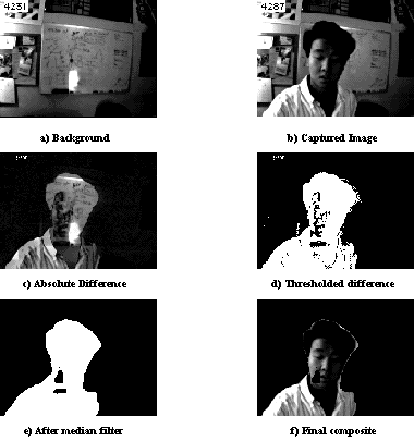
In a 3D environment, we would like to see participants visualized not as rigid planes of pixels, but as silhouettes. For this effect, a background-foreground segmentation step is required, which outputs a binary opacity mask that the graphics engine can use, as shown in figure 5.
Segmentation is performed by the sending client. Our segmentation algorithm is based on the following simplifying assumptions, which are reasonable for our application:
With these assumptions, we can use a simple thresholded-difference approach to segmentation. First, the user captures an image of the unobstructed background. Then, for each image we encode, we compute the absolute difference between the background image and the current image. This difference image is the converted to a binary image using a manually set threshold: all difference values above the threshold value are set to 1, all others are set to 0. The binary image is filtered using a 3x3 median filter to remove noise and gaps. To compute the median of a binary image, we tally up the number of white and black pixels in the window of interest. The larger of the two is the median value. This process is further sped up using lookup-tables on 8 or 16 pixels at time. Figure 6 shows sample output from this algorithm, along with the intermediate images.
The slowest step in this process is the median filter. We have tried approximating the 2D median filter operation as 2 1D operations. Of course, this decomposition is invalid, but the result is similar to the desired effect and is faster to compute.
The segmented image is encoded in the final bitstream by defining pixel value 0 to be background (i.e., transparent), and by changing foreground pixels with value 0 to 1. A flag in the auxiliary data stream indicates that the stream is segmented. This encoding gives us backwards compatibility with regular CU-SeeMe clients. Figure 7 shows a sample screen shot with segmentation active.
The segmentation algorithm can be further improved by using a color video input source. Although the CU-SeeMe video codec discards color information, we can use color information to discriminate between the foreground and background. We have experimented with several color distance metrics, such as distance in UV space and normalized chroma (U/Y, V/Y). We are also exploring the use of multiresolution techniques to segmentation. Evaluating differences at coarser resolutions should help remove artifacts as well as improve performance.
The current implementation renders the 3D scene at about 22 frames/second on a 66MHz PPC601 machine (the lowest end PowerPC). This performance is obtained through standard code-level tricks, such as appropriate use of look-up tables (LUTs) and bit-twiddling operations, and processor specific optimizations, such as

instruction scheduling to keep the execution units of the processor busy. We also use several tricks to improve cache performance.
For instance, large LUTs and large environmental texture bitmaps can hurt cache performance. To address the latter problem, we precompute scaled-down copies of such textures at power of 2 reductions in size, and access the nearest resolution version when rendering. This technique both improves cache performance and provides limited anti-aliasing of the texture.
Another performance optimization is interlacing. Instead of updating the entire 3D window every frame when the viewer is moving, we only update every other row in an alternating, interlacing manner. This method utilizes the eye's decreased sensitivity to detail in motion and increased sensitivity to frame rate. It doubles the rendering speed and also provides a degree of motion blur.
In addition to performance optimizations in the renderer, the VR environment allows us to employ optimizations that reduce the required network bandwidth and the load introduced by video decoding. While a space may be inhabited by many users, a given user only interacts with those in his/her immediate vicinity. Thus, for all users outside of a certain visibility radius, the system removes the request for their AV streams from the reflector. This pruning technique conserves both network and CPU resources. However, we do not shut off the AV streams for those participants that are within the radius, but out of the field of view, or have their backs towards us, because the user can pan faster than the time it takes for the conferencing mechanism to reestablish a video stream.
While the VR client presents a departure from the native user interface of CU-SeeMe, we maintain compatibility with regular CU-SeeMe users. We consider this compatibility important, since it gives us access to the large installed base of CU-SeeMe users. The compatibility is bi-directional: regular CU-SeeMe clients can connect to VR clients, and vice-versa. To the non-VR client, a VR client behaves like a regular, non-VR client. The additional data stream which conveys 3D positional information is ignored by that client. A VR client maps non-VR clients onto a rotating, multifaceted cylinder. This scheme conserves network bandwidth, since at any point in time, only a maximum of half of the non-VR users are visible.
CU-SeeMe permits the participation of users without video (lurkers) that communicate through audio and text. For these users, using both types of clients, we use a default bitmap as a texture map. We also use this bitmap (mirrored) for a normal video client's backside. Without this mechanism, it is difficult to determine which side of a client you are seeing.
CU-SeeMe VR has several limitations. Some limitations can be overcome by adding features; others will require changes in the system architecture. Here, we list the major limitations and our plans to overcome them.
One limitation is that the current system does not allow a large number of users. If more than 10-20 users are in a virtual space, the client will be overwhelmed with video data. To create a virtual world with thousands of users, perhaps in different rooms, new mechanisms to prune unwanted video data must be developed. One solution to this problem is to use IP-multicast to truncate the video broadcast. This can be accomplished by mapping rooms in virtual space to distinct IP-multicast addresses. As a user walks into a new room, they will connect to the IP-multicast address associated with the room. They will see, and be seen by, other users in the room.
Another limitation of the current system is that it uses a fixed file to define the virtual environment. We plan to use scene servers to store the virtual environment associated with a location. Clients can download 3D scene descriptions (probably as VRML data) from the scene servers. Since the scene can be changed by other users (another extension we plan to implement), updates to the scene will be coordinated through the scene servers. These changes will be broadcast on an IP-multicast channel.
Transfer of scene data on initial connection will suffice for small, simple environments. However, downloading large, complex environments with elaborate textures and detailed polygon lists will cause unacceptable delays. We can overcome this problem by progressively transferring scene data and prioritizing the transmission based on the users visibility and/or field of view. Because this scene data is relatively permanent, caching it should be effective.
Aside from storing the state of the environment, scene servers may eventually perform more sophisticated computations, such as, computing a global illumination model for the environment, or generating data for a procedurally animated 3D object.
A third limitation of the current system is the low quality rendering of the virtual world. Although expedient, representing other users as flat video planes is not very realistic or satisfying. We are investigating mapping a user's video onto a three dimensional model of the user (an avatar). Doing so gives rise to many interesting problems that we are just beginning to explore. We would like to compose video captured from multiple camera angles (e.g., front, sides, and back) onto the avatar, so the user can be seen from the front, side, and back. We would also like to adjust the lighting of the video so it is consistent with the virtual world. And, we must control the avatar so that if, for example, the user tilts their head, the head of the avatar also tilts. Two approaches to this problem are sensors, such as data gloves, and computer vision techniques that track the orientation of the person from the video data. A full discussion of these issues is beyond the scope of this paper.
Aside from the technical limitations and problems described in the preceding paragraphs, the effect of the VR metaphor on user interactions is unknown. We have performed only limited user testing to date, and although anecdotal evidence indicates that users are enthusiastic about the new metaphor, the effect of the VR environment on user communications and productivity remains to be seen.
Many important interactions are chance - they occur because one person runs into another in the hall (or at the coffee machine) and strikes up a conversation. A limitation of current video conferencing systems is that they do not encourage such casual interactions. We hypothesize that the VR environment will facilitate such chance meetings as users explore and navigate through the virtual space.
Another open question relates to the utility and limitations of the spatial metaphor. For example, if four people stand in a circle in the virtual environment, each will get a good view of the person opposite and foreshortened or missing views of the people to the left and right. However, such a limitation is not inherent in the technology, but rather in the spatial metaphor, since each client could synthesize a scene that shows the other 3 participants side by side. This solution, however, breaks the spatial metaphor. The real question is which is more important: the communication or the metaphor? We hope to find the answer to such questions with experience in using the system.
Another issue is the mixing of real and synthetic worlds. In the prototype, users are embedded in a completely synthetic world. An interesting question is how to embed a real world into the synthetic world. For example, one might build a virtual "department" with a hallway that has "windows" into offices. Each window would show video captured by a camera on the wall in a real office. Thus, to check if Dave is in his office, you could simply walk down the virtual corridor and look in Dave's window. If he is there, you might walk down the hall to talk to him.
Several intriguing applications of this technology come to mind:
We have presented the design and implementation of a prototype virtual reality conferencing system. Many open questions and problems are posed by such a system, and remain to be studied. These problems include technical problems, such as rendering a more realistic environment, and questions involving the utility and limitations of the VR metaphor. We hope to flesh out the questions and issues raised by this system, and gain some insight into their answers, in future work.
We wish to acknowledge the support of Tim Dorcey, and the rest of the CU-SeeMe development team.
1. Seminatore, M.. A Ray-Casting Engine in C++, in Dr. Dobb's Journal, 232 (July 1995)
2. Dorcey, T. CU-SeeMe Desktop Video Conferencing Software, in Connexions 9, 3 (March 1995)
3. Raggett D., Extending WWW to Support Platform Independent Virtual Reality, in Proceedings of the 5th Joint European Networking Conference (JENC5), 464 (June 1994) pp.2
4. Hewitt K., Desktop Video Conferencing Product Survey, http://www3.ncsu.edu/dox/video
5. Eriksson, H., MBone: the Multicast Backbone, Communications of the ACM 37, 8 (Aug. 1994), pp. 54-60,
6. Sequin, C. H. and Bukowski, R. W., Interactive Virtual Building Environments, in Proc. of Pacific Graphics `95. (Aug. 21-24, 1995) pp. 159-79, 527.
7. Black Sun Interactive, http://www.blacksun.com
8. Fish, R., Kraut, R., and Chalfonte B., The VideoWindow System in Informal Communications, CSCW `90, pp. 1-11
9. McCanne, S. and Jacobson, V., vic: A flexible Framework for Packet Video, in Proc. of Multimedia 95, (San Francisco, Nov, 1995). ACM Press
10. Foley, J., and Van Dam, A., Fundamentals of Interactive Computer Graphics, Addison-Wesley.
11. H. Fuchs, Z. Kedem, B. Naylor, On Visible Surface Generation by a Priori Tree Structures, in Computer Graphics 14, 3 (June 1980), pp. 124-133.
12. Gillilan, R., Cells and Smaller: Exploring the Machinery of Life, demonstration at SUPERCOMPUTING '95, (San Diego, Dec. 1995). http://www.tc.cornell.edu/~ramidon/multimedia.html
13. Begault, D., 3-D Sound for Virtual Reality and Multimedia, Academic Press, Boston, 1994.
14. Takala, T. and Hahn, J., Sound Rendering, in Computer Graphics 26, 2 (July 1992)