The Graphical User Interface
The 2D GUI brings together all the pre-“model
rendering” processes. It handles the user interactions; specifying the proper
file names, tracking points, and bounding boxes for each image. The GUI in addition
to user input also handles the Mosaic and Image factorization steps of the 3D
pipeline. Behind the GUI:
- lies code for extraction of the tracking points and
generation of the *.txt file of those points used by the Image Factorization algorithms
- there is code for clipping the bounding box data and
creating new *.pgm files from the clipped data
- There is code for accessing and viewing the
successive images and actually generating the mosaic of the images.
- There is also code for data interpolation of a user
specified bounding box of the finished mosaic image
The 2D GUI really has two major purposes, one – to create a mosaic image and interpolate the data under a specified bounding area, and two – to create the *.pts file and clipped *.pgm files the 3D GUI needs for rendering the 3D model.
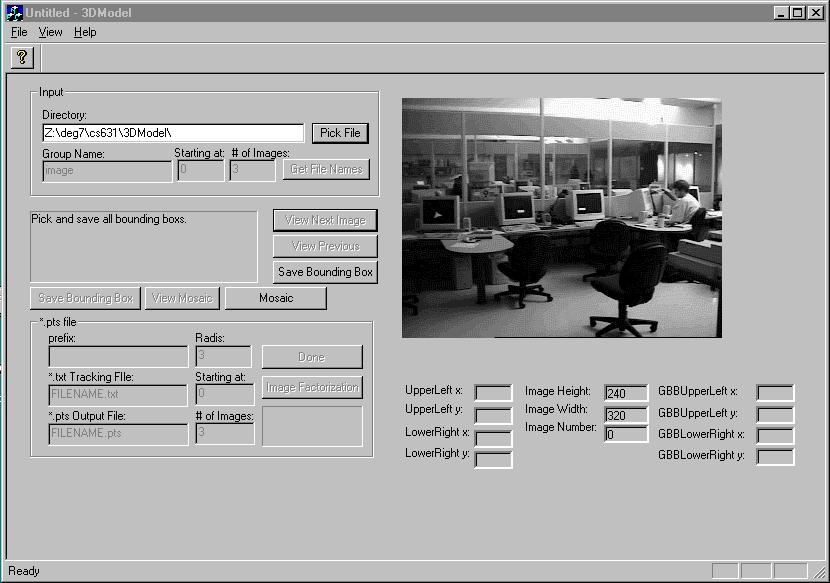
The main features are:
Input Area:
This area allows user to both input a file directory
and group name or to hit the “Pick File” button to bring up a standard Open File
dialog box to search for the file. The input files are set up so that there is a
group name and incrementing numbers following, example CSRoom001.pgm, CSRoom002.pgm
etc. The users can specify what successive subsets of those images are to be used.
Activation Control Area:
This area contains the buttons the user will use to
control the processing of the images.
“View First Image” Button - This button
displays the images in the image display area. It doubles as the “View Next
Image” button, which is self-explanatory.
“View Previous Image” Button – Self
explanatory
“Save Bounding Box” Button – The user
can click the mouse on the image and while the mouse button is down, define a bounding
box, which appears as a dotted rectangle. Hitting this button saves that box into
memory.
“Mosaic” Button - This button makes a call to
the Mosaic2() function with all the user defined *.pgm files. This function creates
a mosaic and saves it as Mosaic.pgm.
“View Mosaic” Button - The finished mosaic is
displayed in the view area.
“Save Bounding Box” Button – This
button, does the same thing as the other of its kind, but also calls a image
reconstruction routine on the bounding area defined by the user on the Mosaic. The
data in the defined bounding area is cut and then interpolated.
Output *.pts Area:
This area allows the user to define the input
parameters for the factorization routine. It then allows the user to run that
routine.
Data Display Area:
This area just gives information on bounding boxes as
the user is constructing them.