A Simple Way to Implement a Bad High Level Synthesis Compiler
Goal
The goal of this project was to experiment with a novel approach to writing a HLS compiler. In particuar we compile Futil, a novel intermediate representation, to Verilog by generating finite state machines that implement Futil's control constructs. This project is divided into two main parts:
- Convert a Control AST in Futil to an intermediate FSM structure
- Generate RTL from the intermediate FSM structure as well as the Futil structure
Background
Futil is made of two sub-languages, a structure language for describing a static computation graph that represents the physical structure of a circuit, and a control language for dynamically choosing which part of the static computation graph runs at a particular time. The ultimate goal of Futil is to be a general framework, similar to LLVM, for working with optimizing HLS compilers. However, the immediate goal of Futil is to provide an Verilog backend for the Dahlia language. This is what we present in this blog.
The structural language is straightforward to convert to Verilog; it already is very close to Verilog. However, the control language does not have a straightforward representation in Verilog. Our plan is to convert these statements into a finite state machine with the same semantics. The finite state machine is then easy to translate into Verilog.
A typical Futil program is shown below:
(define/namespace prog
  (define/component main () ()
==> ((new-std a0 (std_reg 32 0))
     (-> (@ const0 out) (@ a0 in))
     (new-std const0 (std_const 32 2))
     (new-std b0 (std_reg 32 0))
     (-> (@ const1 out) (@ b0 in))
     (new-std const1 (std_const 32 1))
     (new-std gt0 (std_gt 32))
     (-> (@ a0 out) (@ gt0 left))
     (-> (@ const2 out) (@ gt0 right))
     (new-std const2 (std_const 32 1))
     (new-std y0 (std_reg 32 0))
     (-> (@ const3 out) (@ y0 in))
     (new-std const3 (std_const 32 2))
     (new-std z0 (std_reg 32 0))
     (-> (@ const4 out) (@ z0 in))
     (new-std const4 (std_const 32 4)))
==> (seq
     (par
      (enable a0 const0)
      (enable b0 const1))
     (if (@ gt0 out) (enable gt0 a0 const2)
         (enable y0 const3)
         (enable z0 const4)))))
The first arrow is pointing to the structure and the second arrow is pointing to the control.
The structure is an unordered list of two kinds of simple statements: (new-std b0 (std_reg 32 0)) stands for instantiation of the library component b0 with bitwidth parameter 32 and value parameter of 0, and (-> (@ a0 out) (@ gt0 left)) represents wiring the out port of component a0 with the left port of component gt0. The control part specifies which components are active with enable keyword, and the execution logic with par, seq,if, and while keywords. Think of activating a component like a function call. When a component is active it is allowed to run and produce valid outputs.
In this project, we are interested in changing all the control logic to finite state machines (FSMs) and then generating simulatable Verilog program based on both FSMs and the structures.
Design Overview
Futil is the backend for Dahlia. The Futil semantics are designed to allow for easy translation from higher level language, like Dahlia, but this creates a gap between the Futil semantics and Verilog implementations. The table below shows the efforts required to translate the Futil semantics to synthesizable Verilog implementations.
| Futil Semantics | Verilog |
|---|---|
| Invalid wire | Read wires |
| Component Reusing | MUX, Read wires |
| Control | FSM |
Read Signals
In Futil semantics, enable keyword is used to determine whether a component is active. It is the easiest way of translating a program into hardware. However, this implicitly assumes that the signal on a wire is not valid or readable until we enable a component. We therefore require any data wire to have one extra bit to specify whether the signal is readable.
Another way to think about this is that the type of a data wire is Option<T>; the wire is either Some(t) or None, depending on whether the module is enabled.
In order to encode this in Verilog, we add an extra bit to every data wire to encode the tag of the variant.
MUX
A component can be used more than once in Futil. For instance, in the above example,
const0 and const2 are both connected to the input of a0. In Futil, we deal with this by only enabling
a0 and const0, or a0 and const2 at the same time (as seen in the example below).
However, in Verilog the register needs to choose the input from const0 and const2.
This introduces a multiplexer (MUX).
(enable a0 const0)
(enable a0 const2)
At different time steps, read signals tells which wire to the MUX is readable. Therefore, we can use the read wires (the variant tag bit), to serve as sel signals for MUX.
In other words, this MUX can be thought of as a function List<Option<T>> -> T that chooses a Some(t) from a list of options. We assume that only wire feeding into a MUX will be valid at a time.
FSM
In Futil, there are control constructs like if, while etc. These can be translated into FSM in Verilog implementation, which is the main goal of this project. However, before getting to that, we created intermediate FSM expressions in Futil. An FSM component has:
- input and output ports,
- connection of wires between its own ports and other components' port,
- internal control logic that determines the output signals.
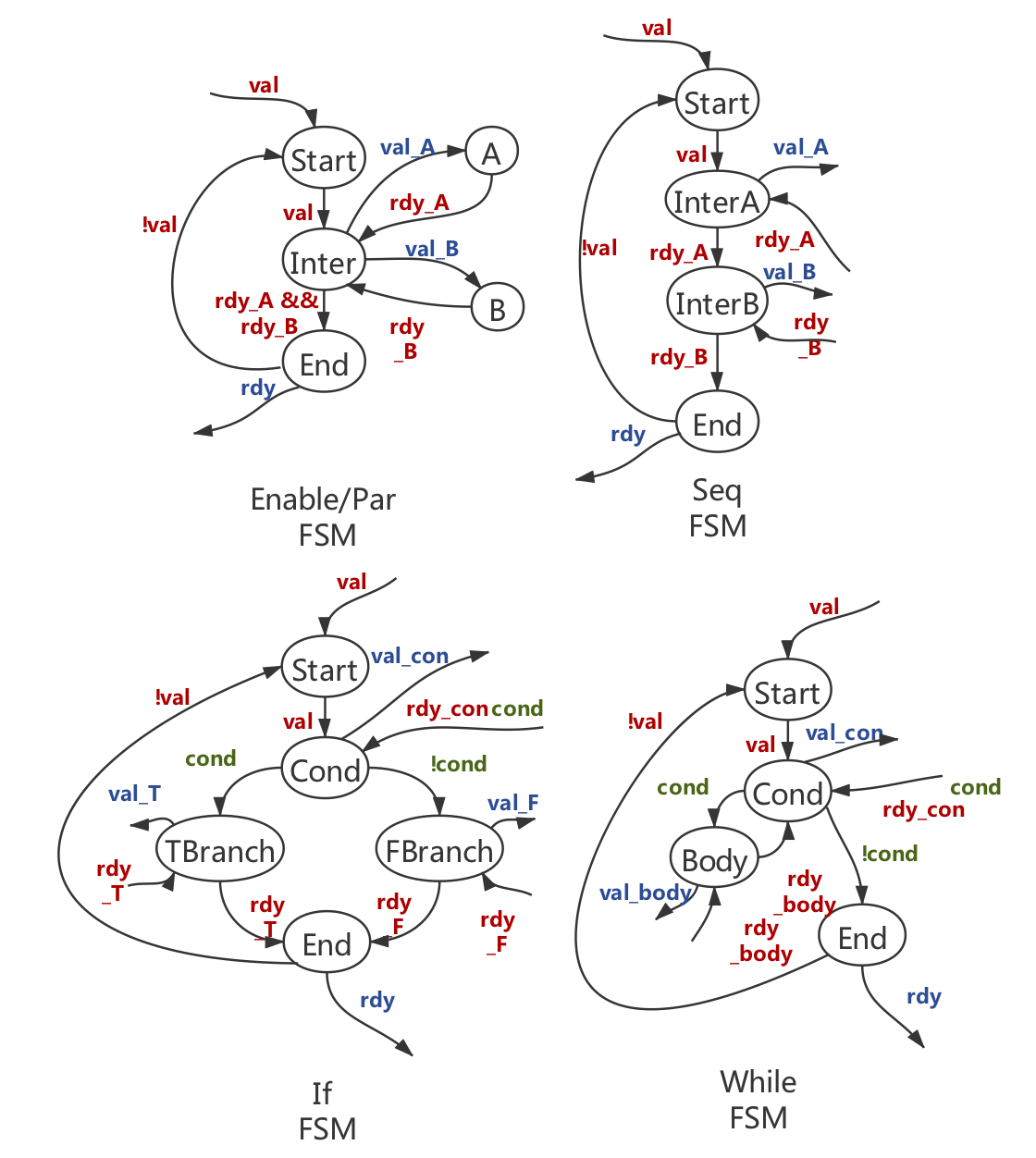
The internal control logic of a FSM component can be divided into several states that determine the output signals. A state transfers to another according to some input signals. In general, all FSM components are composed of one Start state, some Intermediate states and one End state.
Consider the syntax (enable A B). The Start state transfers to the Intermediate state when the valid signal is high. At the Intermediate state, the FSM sends out valid signals to subcomponents A and B, and waits for ready signals from them to be high. Once both of the ready signals are high, the FSM transfers to End state and outputs ready signals to notify any components waiting for this component to finish. It transfers back to Start state when the valid signal is low, indicating the upper components have received the ready signal and finished execution so it is safe for the FSM to go back to the Start state. The same design logic applies to all FSMs. The only difference happens in intermediate state(s): the seq FSM has one or more intermediate states and one intermediate state only transfers to next state when receiving a high ready signal from the previous state; the if FSM sends valid to the module that executes the comparison and receives both ready and condition signals which determine the state it should transfer to; the while FSM transfers to loop Body state when the condition signal is high and goes to End State when the condition is low.
Implementation

To realize what we describe in design overview, we gradually added intermediate passes.
First Intermediate Pass
There is a Visitor trait in this pass, which performs a recursive walk of abstract syntax tree (AST), so each individual pass can perform modification to the AST with function calls including add_structure, add_input_port, remove_structure, etc.
Read Wires
The first pass is adding read wires. We go though all input and output ports of each component, adding corresponding read ports, and then each wire of the components and adding read wires to the ports. We do this pass ahead of creating FSM signatures because we don't want to create read wires for control signals like valid and ready.
FSM Signatures
This pass translates control syntax to FSM components.
Based on the design logic of FSMs, we can specify the inputs and outputs of each FSM component and the wires connecting each ports to its subcomponents. Notice we also need to add cond_read signals to specify whether the condition signal from the comparison component is readable.
| FSM | Input Ports | Output Ports |
|---|---|---|
enable/par/seq | val, rdy_A, rdy_B, ... | rdy, val_A, val_B, ... |
if | val, rdy_con, cond, cond_read, rdy_T, rdy_F | rdy, val_con, val_T, val_F |
while | val, rdy_con, cond, cond_read, rdy_body | rdy, val_con, val_body |
Interfacing
This pass creates input port clock for all components and valid for the top level component. Notice in Futil, we do not have an explicit notion of time steps. However, to make things easier for RTL translation, we created these ports.
MUX Signatures
Similar to creating FSM signatures, we need to specify the inputs and outputs of each MUX component and the wires connecting each ports to its subcomponents. To do this, we create a Hashmap indexing with destination ports and store a vector of source ports according to the wiring of the component. For each destination port, if there is more than one source port connecting to it, we create a MUX.
Notice there is a difference between control signal and data signals though. Control signals do not have corresponding read wires and no matter which control signal is high, the output is high. On the other hand, data signals always have corresponding read wires to explicitly specify if the data on the data wire is readable. The data signal should be chosen according to its read wires. Therefore at implementation, we go through wires twice. The first time we go through it we record read wires going to the same destination components. The second time we go through it we actually create the large MUX with both data and corresponding read wires.
The last step is removing old wires connecting the same destination port with more than one source port.
Second Intermediate Pass
FSM Implementation
This pass creates true FSM representations in Futil AST. Each FSM has a name field, a states Hashmap storing states and indexing of the state, a start index corresponding to the first state being created and a last index pointing to the last state being created. Each State is composed of a vector of outputs, where each output is specified with output value and port name and a vector for transitions, where each transition is a tuple of next state index and inputs of value and port name, so that the transition happens when the input has certain value. Finally, there is a default state for each state that is an optional field, telling which state it should transition to when no transition condition is met.
We provide abstract methods new(name: &str) -> StateIndex, new_state() -> StateIndex, get_state(idx: StateIndex) -> &mut State for FSM and push_output(output: ValuedPort)and add_transition(transition: Edge) for State to generate actual FSM inner logic according to the graph we made in design review.
FSM to RTL generation
After generating an FSM, we need to translate the entire structure of inputs, outputs and states to synthesizable hardware using Verilog. This is done by breaking down a Verilog file into distinct components.
- Module Declaration: Here we define the name of the module along with the inputs and outputs for it.
- Wire/reg definitions: These are internal signals that are used within the module.
- FSM: FSMs can be represented in Verilog using 3
alwaysblocks - State transition, Next state logic, State outputs.
To expand on how all the 3 always blocks are generated we discuss them below:
- State transition: This is pretty standard. It actually changes the state at a clock edge. Since this is a generic block it can be created without any inputs.
- Next state logic: This block has a bunch of cases for all the states. For each state in the FSM struct, based on the input transitions to it, we have
if elsestatements for next state logic. - Output logic: This block contains output signals for each state represented by cases, similar to the previous block. In addition to having Verilog statements for all the relevant outputs in the state, we also assign the rest of the outputs of the FSM to be zero for now. This is done to avoid inferred latches, which can occur if all outputs are not assigned in each state even though they don't change.
We used a Wadler-style printing api provided by the pretty rust crate to format the Verilog files.
Hardest Parts
- Futil is implemented with Rust, so we spent some time to get familiar with the language.
- The design of the FSM representation changed multiple times. Because the state should be stored as pointer and then modified when we add transitions and outputs to it. Rust will force the user to use reference counting, which we did not realize at first. Also, even with reference counting, we would have to create reference cycles which would prevent the FSMs from being freed. We therefore used on HashMaps in the end.
- Futil read signals are not common in Verilog coding convention. We had two models in our minds: the Verilog valid/response model and our Futil valid/read model. We messed things up because of the existence of the two models and spent a huge amount of time discussing which one should be the most ideal design.
Evaluation
We evaluated our compiler by simulating the generated Verilog. We generated Futil programs with a simple backend we wrote for the Dahlia compiler. The Verilog simulation was donew with an open source tool called Verilator which turns Verilog into a C++ object that you can link to, manipulate
the inputs, and watch the outputs. This generates a .vcd file that you can view in a wave form viewer like gtkwave. From here you can explore the values of different wires across time.
Although we got the core of the compiler working, we weren't able to test very complicated Dahlia programs because we did not implement memories. We also do not correctly generate the logic to multiplex between different inputs to a single component so we were not able to fully take advantage of the parallelism that hardware can provide. Despite these problems, we were still able to get some programs working. Below is a very simple program that simply checks whether a number is greater than 5.
let a = 10;
let b = 1;
---
if (a > 5) {
  let y = 20;
} else {
  let z = 40;
}
Below is an almost equivalent Futil program. We've drawn an arrow to the difference between the two. This statement simply performs the comparison b > 5 using the same comparison component as the one used in the condition of the if statement. We've made this change to prove that we can use the same module multiple times. Although this sounds simple, it actually requires muxing between the control signals produced by two different FSMs. We also have to generate muxing between a0 and b0.
(define/namespace prog
  (define/component main () ()
    ((new-std a0 (std_reg 32 0))
     (-> (@ const0 out) (@ a0 in))
     (new-std const0 (std_const 32 10))
     (new-std b0 (std_reg 32 0))
     (-> (@ const1 out) (@ b0 in))
     (new-std const1 (std_const 32 1))
     (new-std gt0 (std_gt 32))
     (-> (@ a0 out) (@ gt0 left))
     (-> (@ b0 out) (@ gt0 left))
     (-> (@ const2 out) (@ gt0 right))
     (new-std const2 (std_const 32 5))
     (new-std y0 (std_reg 32 0))
     (-> (@ const3 out) (@ y0 in))
     (new-std const3 (std_const 32 20))
     (new-std z0 (std_reg 32 0))
     (-> (@ const4 out) (@ z0 in))
     (new-std const4 (std_const 32 40)))
    (seq
     (par
      (enable a0 const0)
      (enable b0 const1))
---> (enable gt0 b0 const2)
     (if (@ gt0 out) (gt0 a0 const2)
         (enable y0 const3)
         (enable z0 const4)))))
This simple program results in a whopping 969 lines of Verilog code (which I will not paste here). We simulated the code in our simple test bench and were able to generate the following signal diagram:
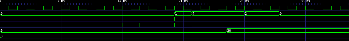 From top to bottom, the signals are:
- clock
- state of the fsm for the if control statement
- output of the greater than comparison component
- read output signal for the greater than component
- the value in the y register
- the value in the z register
Notice that the read output signal goes high twice. The first one corresponds to the first time we do the comparison and the second time it goes high is for the comparison in the condition of the if statement.
From this diagram, we can see that the true branch of the program was correctly taken and that value 20 was put into the register y. The z register remains in its default state.
For a slightly more interesting example, and because it is the classic hello world program of hardware, we implemented a counter. The Dahlia code is the following:
let i = 0;
---
while (i < 10) {
  i := i + 1;
}
and the equivalent Futil code:
(define/namespace prog
  (define/component main () ()
    ((new-std i0 (std_reg 32 0))
     (-> (@ const0 out) (@ i0 in))
     (new-std const0 (std_const 32 0))
     (new-std add0 (std_add 32))
     (-> (@ i0 out) (@ add0 left))
     (-> (@ const2 out) (@ add0 right))
     (new-std const2 (std_const 32 1))
     (-> (@ add0 out) (@ i0 in))
     (new-std lt0 (std_lt 32))
     (-> (@ i0 out) (@ lt0 left))
     (-> (@ const1 out) (@ lt0 right))
     (new-std const1 (std_const 32 10)))
    (seq
     (enable i0 const0)
     (while (@ lt0 out) (lt0 i0 const1)
       (enable i0 add0 const2)))))
Running the resulting 509 lines of Verilog code gives us the following trace:

Finally, we got a simple implementation of Fibonacci running. Here is the Dahlia code:
let a = 1;
let i = 0;
---
let b = 1;
---
while (i < 10) {
  let tmp = b;
  i := i + 1;
  ---
  b := a + tmp;
  ---
  a := tmp;
}
Notice that we have a lot more triple dashes than Dahlia requires. This is because without them we run into the aforementioned problems with muxing.
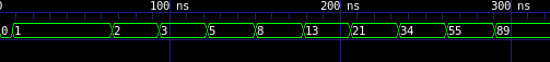
Our compiler resulted in 1412 lines of Verilog code. I compared this against the equivalent C++ program compiled with the Vivado HLS toolchain. Their compiler resulted in 148 lines of Verilog code. Although this is an imperfect metric, it does show that this method of compiling to hardware has a large overhead.
Conclusion
Overall this was a very interesting project. Although the overhead of this approach is very high, we successfully demonstrated that you can build a simple but functional HLS compiler in ~2 weeks with this approach. Additionally, because most of the compilation work took place within Futil, it would be straightforward to improve the quality of the output by writing more passes. I think that this provides an excellent baseline so that we can explore the impact of more optimizations.