CS5625 PA5 Reflection Mapping
Due: Friday March 18, 2015 at 11:59pm
Work in groups of 2.
Overview
In this programming assignment, you will implement:
- a shading model for a perfect mirror material taking a cube map as the source of incoming light,
- a system for rendering the scene into a cube map so that it can be used with the shading model in the previous item,
Task 1: Reflective material from cube map
Edit:
- student/src/shaders/forward/reflection.frag
- student/src/pa5/ForwardRenderer.java, especially the renderMeshPart method that takes ReflectionMaterial as argument
The ReflectionMaterial material class contains two important fields:
- cubeMap, which represents the environment map, and
- worldToCubeMap, which is a 3x3 matrix that transforms a direction from world space to cube map space. We shall refer to this matrix as $M_{\mathrm{world}\rightarrow\mathrm{cube}}$. This matrix is used so that different instances of the material can reflect a differently "rotated" version of the cube map.
Let us first discuss how the reflective material works. Suppose, at the shaded point, we have a computed the direction the direction $\mathbf{r}_{\mathrm{cube}}$, which represents the direction that a perfect mirror should reflect the view direction from its surface. Then, the fragment color of the shaded point is simply given by:
gl_FragColor = textureCube(mat_cubeMap, $\mathbf{r}_{\mathrm{cube}}$);
How do we get $\mathbf{r}_{\mathrm{cube}}$? The fragment shader is given two varying variables geom_normal and geom_position, so we can compute a view direction and a normal vector from it. Since these uniforms are in camera space, the resulting vectors are also in camera space, which we shall denote by $\mathbf{v}_{\mathrm{cam}}$ and $\mathbf{n}_{\mathrm{cam}}$. From these vectors, we can compute the reflected direction $\mathbf{r}_{\mathrm{cam}}$, which is also in camera space. (As a note, you can use the GLSL built-in reflect function to compute $\mathrm{r}_{\mathrm{cube}}$, but BE VERY CAREFUL OF WHAT IT EXPECTS AS ARGUMENTS.) This is not exactly what we want because we want the vector in the cube map space.
To get the vector in cube map space, first realize that, if $\mathbf{r}_{\mathrm{world}}$ is the reflected direction in world space, then $$ \mathbf{r}_{\mathrm{cam}} = M_{\mathrm{view}} \mathbf{r}_{\mathrm{world}}. $$ In other words, $$ \mathbf{r}_{\mathrm{world}} = M_{\mathrm{view}}^{-1} \mathbf{r}_{\mathrm{cam}}. $$ Once we have the vectors in world space, we can use $M_{\mathrm{world}\rightarrow\mathrm{cube}}$ to transform them to the cube map space: \begin{align*} \mathbf{r}_{\mathrm{cube}} &= M_{\mathrm{world}\rightarrow\mathrm{cube}} \mathbf{r}_{\mathrm{world}} = M_{\mathrm{world}\rightarrow\mathrm{cube}} M_{\mathrm{view}}^{-1} \mathbf{r}_{\mathrm{cam}}. \end{align*}
Next, let us discuss the source of the cube map. The interface TextureCubeMapData represents an object that can fulfill the functionality. It is implemented by two classes for two different situations:
- The FileTextureCubeMapData class represents a cube map that is constructed from 6 images located in storage. We will be concerned with only this class in this task.
- The RenderedTextureCubeMapData class represents a dynamic cube map that is renderered each frame. We will work with this one in the next task.
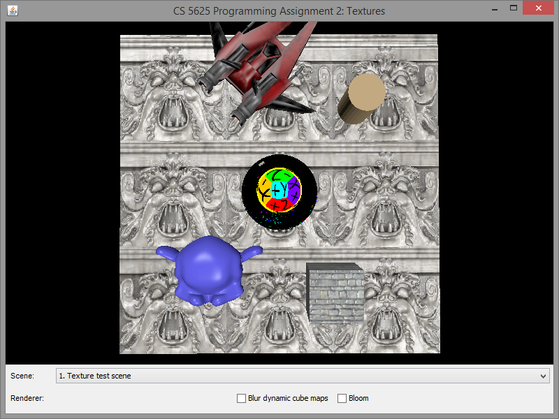
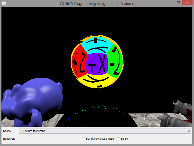
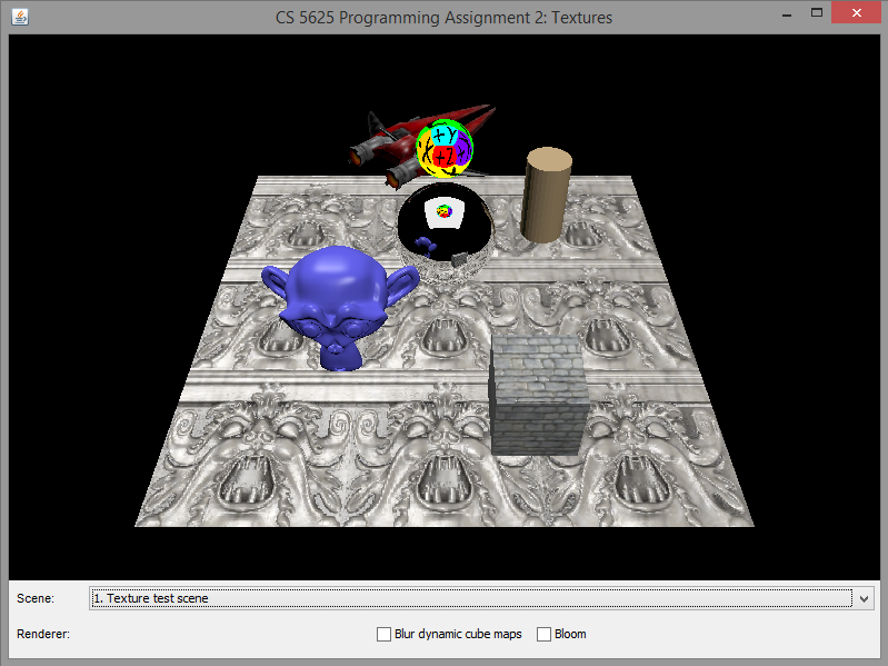
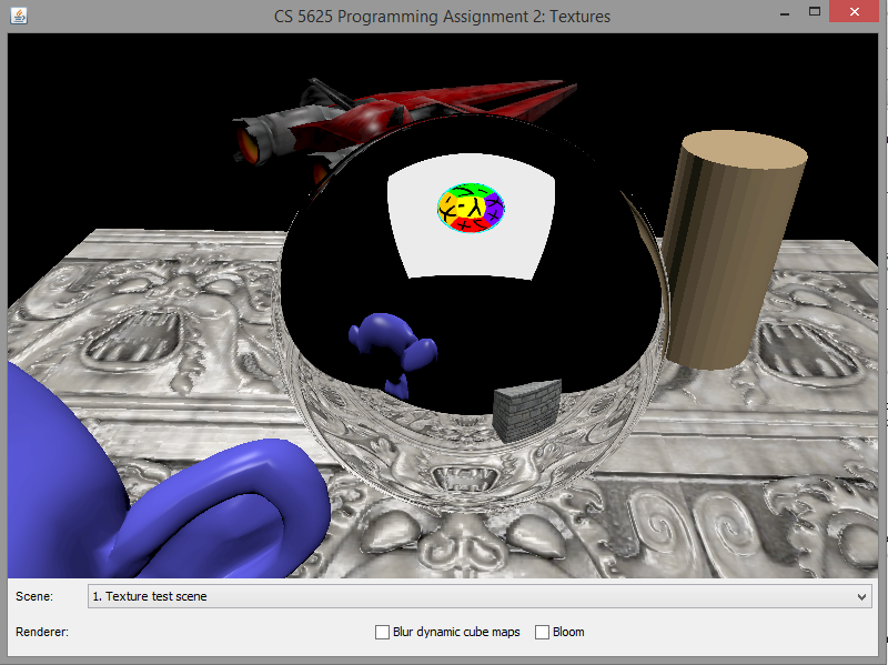
A correct implementation of the cube map should produce the following appearance on the top sphere:
 |
 |
 |
 |
Note that, since we have not implemented the dynamic cube map, the bottom sphere would display some random images depending on the contents of the GPU memory before the program ran. As such, the images displayed by your program might be different from what are shown in the example images above. This is not an issue, and you should proceed to the next task.
Task 2: Dynamic cube map
Edit:
- the renderCubeMapProxies method in the ForwardRenderer
How a cube map should be rendered is determined by the CubeMapProxy object, which represents an imaginary cube located in the scene. A CubeMapProxy has a name by which the RenderedTextureCubeMapData refers to it. It also has information on the resolution of the cube map and other rendering parameters.
The ForwardRenderer locates all the CubeMapProxy objects in the scene using the collectCubeMapProxies method. It stores the proxies in a HashMap called cubeMaps so that they can be indexed by name. For each proxy, it creates an auxiliary object of class CubeMapInfo that contains several objects useful for cube map rendering:
- proxy is the CubeMapProxy itself,
- node is the SceneTreeNode containing the proxy,
- cubeMapBuffers is a collection of buffers in which the cube map will be rendered into,
- textureRectBuffers is a collection of buffers made of TextureRect, having the same size as a side of the cube map.
To render a cube map, you should iterate through its six sides. For each side, set up the camera so that:
- The camera is located at the center of the cube.
- It looks through the correct side of the cube.
- When setting up the perspective camera, set the near clip to the distance between the center and the side, and set the far clip to the farClip field of the CubeMapProxy object.
Due to the filtering that we will be performing in the next section, we advise that you render to the textureRectBuffers first, then copy the resulting content to the appropriate side of cubeMapBuffers.
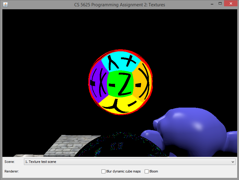
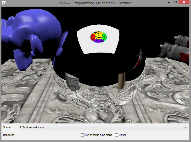
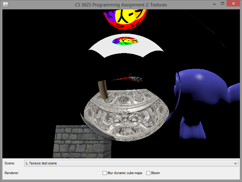
A correct implementation of the dynamic cube map rendering should produce the following images:
 |
 |
 |
 |
Task 3: Cube map filtering
We have implemented a mechanism for dynamic cube map in the last task, which allows us to simulate a mirror-like object being embedded in the scene. One way to simulate roughness of the material's surface is to blur the cube map. In this way, the higher the blurring, the rougher the surface becomes.
Edit:
- student/src/shaders/gaussian_blur.frag
- the renderCubeMapProxies method in the ForwardRenderer
In the last task, you should have rendered the scene to the textureRectBuffers before copying the resulting image to the appropriate cube map side. In this task, before copying the image to the cube map, you should run the Gaussian blur shader to the rendered image two times, one for the x-axis and another for the y-axis, if the dynamicCubeMapBlurringEnabled field is set to true.
The gaussian blur fragment shader should implement a 1D Gaussian blur. To get a 2D blur, you have to apply it two times. The shader contains the following uniforms that specify the Gaussian kernel:
- size is a half of the width of the window of the kernel. Namely, when performing convolution, the shader will only look at the $2\cdot \mathrm{size} + 1$ pixels (in the appropriate direction) centered at the pixel specified by geom_texCoord.
- stdev is the standard deviation ($\sigma$) of the Gaussian kernel. Its unit is "pixel width."
- axis specifies the axis to apply the Gaussian blur. The value of 0 indicates the x-axis, and the value 1 indicates the y-axis.
- set size to the gaussianKernelSize field of CubeMapProxy,
- set stdev to the gaussianKernelStdev field.
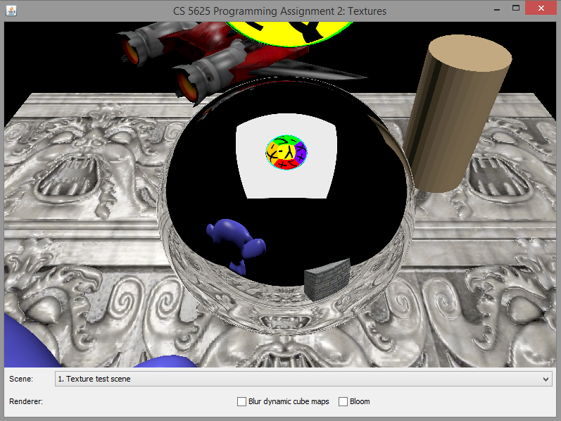
A correct implementation should yield the following differences between the rendered images:
 |
 |
| No blurring | With blurring |