Scene Graphs
As designers, we are not expecting you to write (much) code in this course. But any work that you can do to remove work from the programmers is much appreciated. So that is why this lab is going to teach you how to make your own scene graphs using our JSON specification language. With this tool you can create the visuals for a UI element or complicated scene, and then hand it over to the programmers to hook it up to code.
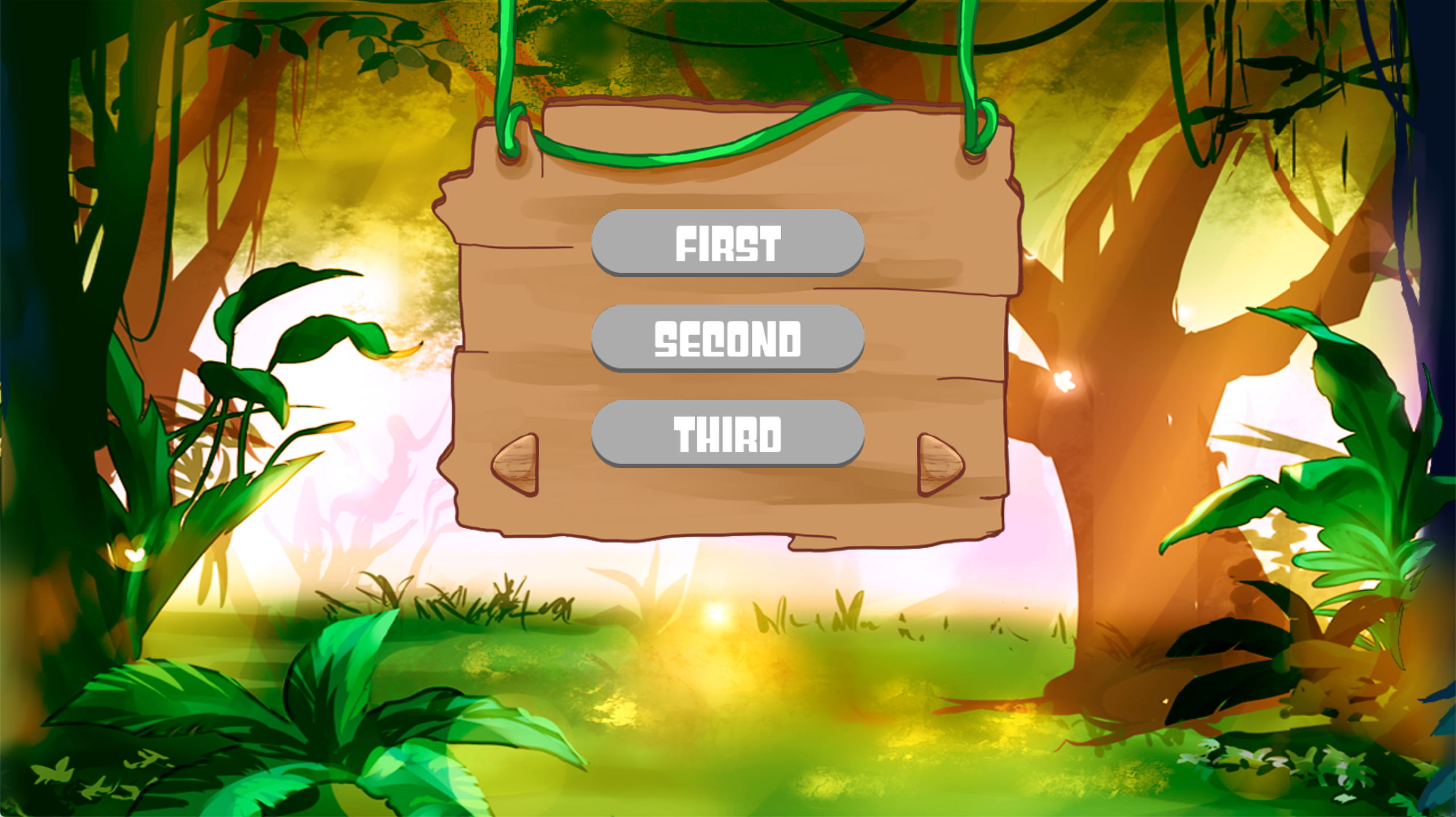
To help you with this assignment, we recommend that you read the CUGL Scene Graph Tutorial. This document was created by a TA several years ago to help designers create scene graphs in JSON.
Because of the length of this activity, we have actually broken it up over two labs. In fact, when you complete the lab, you will not have the picture illustrated above. You will only complete part of the scene this week, getting as far as the picture below. You will complete the remainder in the next lab.
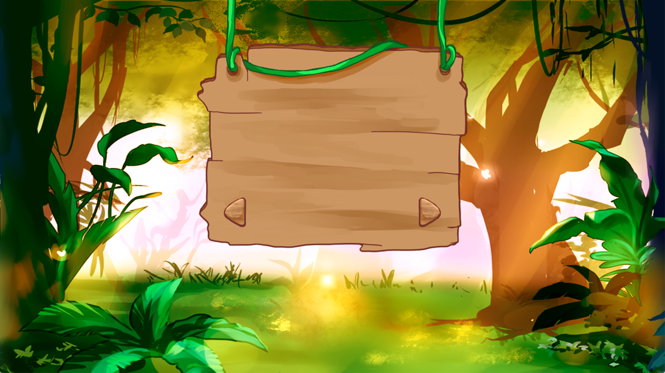
As a reminder, this assignment is graded in one of two ways. If you are a 4152 student, this is graded entirely on effort (did you legitimately make an attempt), and that effort will go towards you participation grade. If you are a 5152 student, you will get a more detailed numerical score.
Table of Contents
Useful Resources
Through this assignment we will assume that you already understand two concepts: aspect ratio and JSON files. Both of them are fundamental concepts to this lab. If you are not familiar with them, then you should refer to the resources below. Even if you are familiar with them, we still recommend that you check out the JSON validator.
Aspect Ratios
If you do not know what an aspect ratio is, the link above provides a quick overview of the topic from Adobe. This overview talks about why it is important for web pages and how to make a web page that is aspect ratio aware. Because your games will be on mobile devices, the same is true for the games that you develop.
With that said, there are some standard aspect ratios that you should be prepared for in this class. They are as follows:
- 16x9: Android phones, PC Gaming
- 16x10: Android tablets
- 19.5x9: Modern iPhones
- 3x2: Old iPhones (pre iPhone 5)
- 4x3: Most iPads
- 21x9: Ultra-wide gaming monitors
JSON Tutorial
If you do not know what a JSON file is, then the above tutorial is an excellent resource for how to use them. As a designer, you do not need to know how to use JSON files in Javascript (or C++ for that matter). But you do need to know how to write a valid JSON file with no errors in it.
For those of you who have taken Python, you will notice that JSON files look pretty
much like (nested) Python dictionaries. And this is a helpful way to think about
them. However, in Python all strings must have double quotes, not single
quotes. Furthermore, all booleans are lower case (so true instead of True).
JSON Validator
When you write your JSON files, this files will have errors in them. And 90% of those errors will be the result of a comma: either a comma that is missing or an extra unexpected comma. While CUGL does provide you with error messages when this happens, it can be hard to read these error messages if you are not used to programming.
That is why it is always best to test your JSON files in the JSON validator above. If the JSON file is malformed then it will tell you why and where. Passing the validator does not guaranteed that your JSON is correct. You may have misnamed a key, or forgotten a data value. But at the very least it will guarantee that your JSON will not cause the game to crash.
CUGL Scene Graph Tutorial
Once again, this is a complete documentation of the JSON format used to create scene graphs. While this lab will take you through most of the process, it is handy to keep this document around as a reference. We have made several edits to make it match the current version of the CUGL engine. However, if anything in the tutorial is wrong, please let us know.
The Scene Tool
While we are not expecting you to compile code for this lab, we do need you to run a CUGL application. You should already have experience with this from the previous lab. If you were able to get the animation tool running, you will have no problem with the scene tool. If you did the last lab without ever running the animation tool, we recommend that you go back and get it working, as we will not provide you with new instructions here.
As with the animtion tool, you should download the correct tool for your platform:
- macOS: SceneToolMac.zip
- Windows: SceneToolWin.zip
In both cases you run the application by typing the name SceneTool.exe. On some platforms
you may need to add an extra ./ like ./SceneTool.exe.
IMPORTANT: On macOS, remember to validate the application by typing the command
xattr -cr SceneTool.exe
Project Overview
Aspect Ratios
One of the key things about this lab is to make sure that your scene graph looks correct
no matter the aspect ratio of the device. You can simulate that in this lab by altering
the size of the game window. Everything that you need in this lab is located in the
assets folder. Look at the file resolution.json in the subfolder boot. You will
see the following code:
{
    "position":   "centered",
    "resolution": [1280,720]
}
To change the size of the screen, edit the resolution numbers. For example, if we wanted to create a 4x3 aspect ratio, we could edit the JSON as follows:
{
    "position":   "centered",
    "resolution": [960,720]
}
To see how the resolution changes, save the JSON file and run the scene tool again.
You can also change the position of the window on your screen so that it is not centered. Simply give a position like this:
{
    "position":   [50,50],
    "resolution": [960,720]
}
The position represents the number of pixels that the top left corner of the window will be from the top left corner of your monitor.
Scene Graphs
Before you start editing the JSON files, we need to give you a brief overview of scene graphs in general, as well as what this lab’s scene graph should look like when you are finished editing it. For a more in-depth lesson on scene graphs, you can also check out the [lecture for COVID] (https://courses.cis.cornell.edu/courses/cs4152/2021sp/lessons/secure/6/) and its accompanying resources. However, we will be giving this lecture in the next week and we hope that it is not necessary
To understand how a scene graph works, you can map out the structure with a tree. Every scene graph has a root node that is the size of your screen.
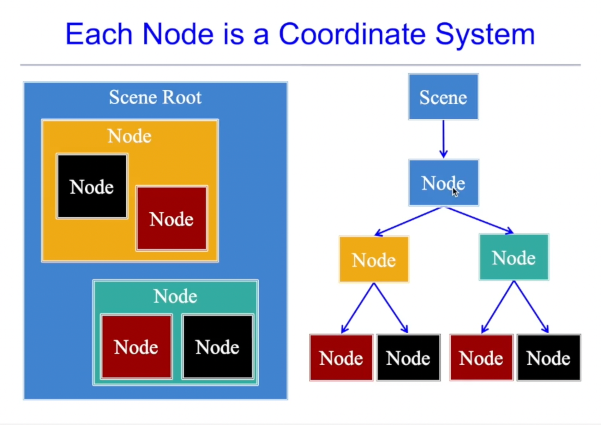
Each node uses coordinates that are relative to its parent. This means that if you move or rotate the parent node, the children of that node will also change with it. For example, if you have a window with buttons in it, the buttons will move as the you move the window. The origin of node is always the bottom left corner.
In this lab, the scene has been named “lab”. You will be completing the scene by editing
the assets.json file and adding children to its root node. By the end of this lab, you
should have a scene with elements that are arranged like this:
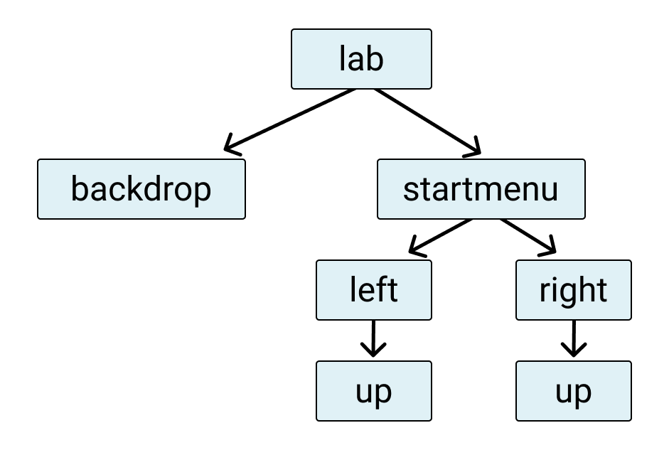
Each node does the following:
backdropwill display the scene’s backgroundstartmenudisplays the menu backdropleftandrightare buttons within the menuupis what to shown when these buttons are up (not down)
Within each node, you will be setting parameters that give it its position, size, and more.
Layout Managers
The scene graph is only part of the picture. In order to make your application responsive to different aspect ratios, we also have what are known as layout managers. Instead of giving a node a specific location in your application, you want some way to specify how the application changes as the aspect ratio changes.
The layout manager that you will be working in the class is the anchor layout. This is a layout in which nodes are placed at one of the borders (or in the center of the screen). For example, if we place two nodes – one at the top left and one in the bottom right, then they will adjust as shown below:

When specifying an anchor, we do not use pixel coordinates, since we do not know the size of the screen. Instead, we specify everything in terms of percentages. So (0,0) is the bottom left corner, while (1,1) is the top right corner. The anchor (0.5,1) would be the top center. This is shown below.
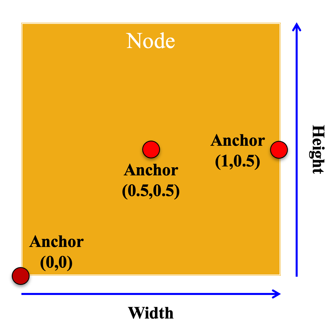
The other important thing to wrap your head around is that anchor layouts require two anchors at all times. There is the anchor for the parent, which means the place to put the child. Therei is also the anchor for the child, which is the part of the child to put at the given location. So if the parent had anchor (0,1) and the child had anchor (0.5,0.5) this would anchor the center of the child in the top left corner of the parent.
The JSON Description
In CUGL, all scene graphs are specified with JSON files.The scene that you are working
with is in located in the file assets.json. If you look at this file, you will see
the following
"scene2s" : {
    "lab": {
        "type"      : "Node",
        "comment"   : "This is the root node of the scene for the lab",
        "format"    : {
            "type" : "Anchored"
        }
    }
}
The JSON object "scene2s" is the list of scene graphs for this game. There is only
one scene graph, which is called "lab". Its root is a simple node with an anchor layout.
You should never delete the lines you see above. Instead, everything that you create
will be a child or a descendent of that node. Because of how assets work in CUGL, you will
need to restart the application every time you change this file.
If you look at the files, you will notice another JSON file called "loading.json".
This is the loading screen with the CUGL logo at the beginning. Do not modify this file.
However, this file is a good reference for you to look at it if you are ever getting
stuck.
Instructions
Once you have figured out how the project all fits together, it is time to start making changes. We recommend that you make the following changes in order.
1. Add a Background Image
You need to add a child node to "lab". You do that as follows:
"scene2s" : {
    "lab": {
        "type"      : "Node",
        "comment"   : "This is the root node of the scene for the lab",
        "format"    : {
            "type" : "Anchored"
        },
        "children" : {
            ...
        }
    }
}
Your child node will go where the ... are.
Let’s call this child node "backdrop". The node "backdrop" will have no children,
but it will have three entries: type, data, and layout. The value type is a string,
while data and layout at JSON objects, so they contain data in between two curly braces,
like this:
"backdrop": {
    "type": ...,
    "data": {
        ...
    },
    "layout" : {
        ...
    }
}
Now for the details. Your type is "Image", as this is a background image. For the
data, you want the texture to be "background". This is a name of a texture defined
higher up in the assets.json file. All images have to have corresponding entry in
the "textures" JSON object. You write this texture inside of "data", with the
key "texture".
You also use "data" to specify the anchor of your scene graph. We talk about
anchors above, but remember that it is point expressed as a
percentage of the size of the node. So (0,0) is the bottom left corner, while (1,1)
is the top right When specifying a point in a JSON file, you use square brackets.
Therefore, to set the anchor to the middle of the image, you would use
"anchor": [0.5,0.5]
However, we do not want you anchoring the image in the center. This particular image is designed to look better if you anchor on the left and always crop on the right (instead of cropping on both sides). So you should set the anchor to the center left (using what we told you above).
Setting the anchor point is only half of using an anchor layout. You also need to
set the layout values "x_anchor" and "y_anchor" inside of "layout". These
correspond to the parent anchor. But this time we have more options than a single
point. In particular, we want the "y_anchor" to be "fill". This will stretch the
image so the top and bottom perfectly fit the screen.
But we do not want to set "x_anchor" to "fill", as that will squoosh the image (which is
very large to support all aspect ratios) on to the screen, distorting it. Instead, we want
to guarantee that the left edge of the image is always on the left edge of the screen.
You have already defined the anchor to be the left edge of the image. Now set "x_anchor"
to "left" to put it there.
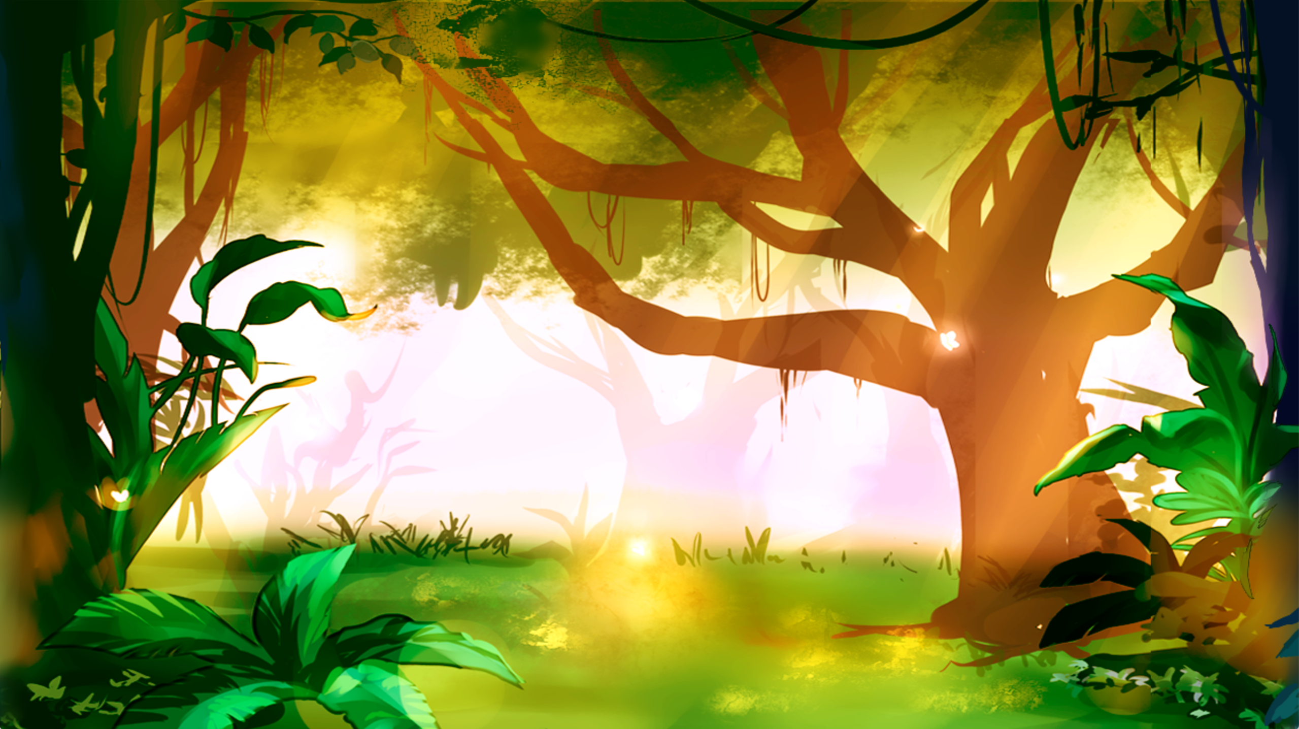
Assuming that you have done everything correctly, run the screen tool. Now the default aspect ratio (16x9) will look like the image below.
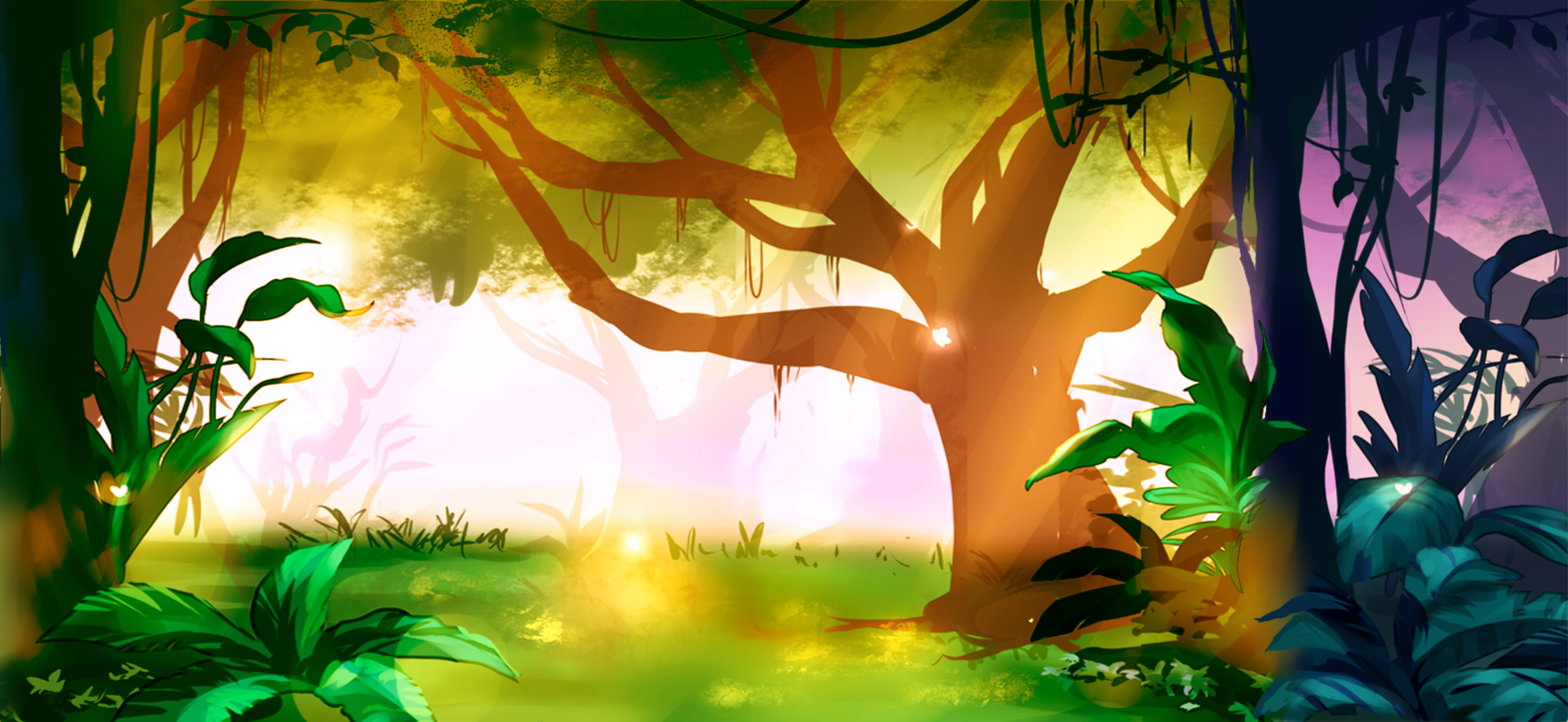
You should check that your image is correctly anchored and sized for multiple aspect ratios. For example, for 19.5x9 (iPhone), it should look like this
If your game crashes when you run it, make sure to check your JSON with the JSON Validator. The biggest problem people run into is forgetting commas. Remember that you have to have commas between all entries, but that the last entry in an object or an array should not have a comma after it. If you are running the tool properly, the error message should tell you where to look in the JSON file for your problem.
Remember that you can always look at the file "loading.json" as a reference.
This is moderately sophisticated scene graph with a logo and a button. Otherwise,
feel free to come to office hours for help.
2. Add the Menu Backdrop
You should now make another child of "lab" called "startmenu". It will use the
texture "menuboard". It should also have a "scale" value of 0.8 (this means it
will be 80% of its normal size).
We want to anchor this menu to the center top of the screen. To do that you set
the "anchor" position in "data" to be the value for center top. In addition,
you set the "layout" values "x_anchor" and "y_anchor" to be "center" and
"top", respectively.
When you are done, the 16x9 version should look like this.
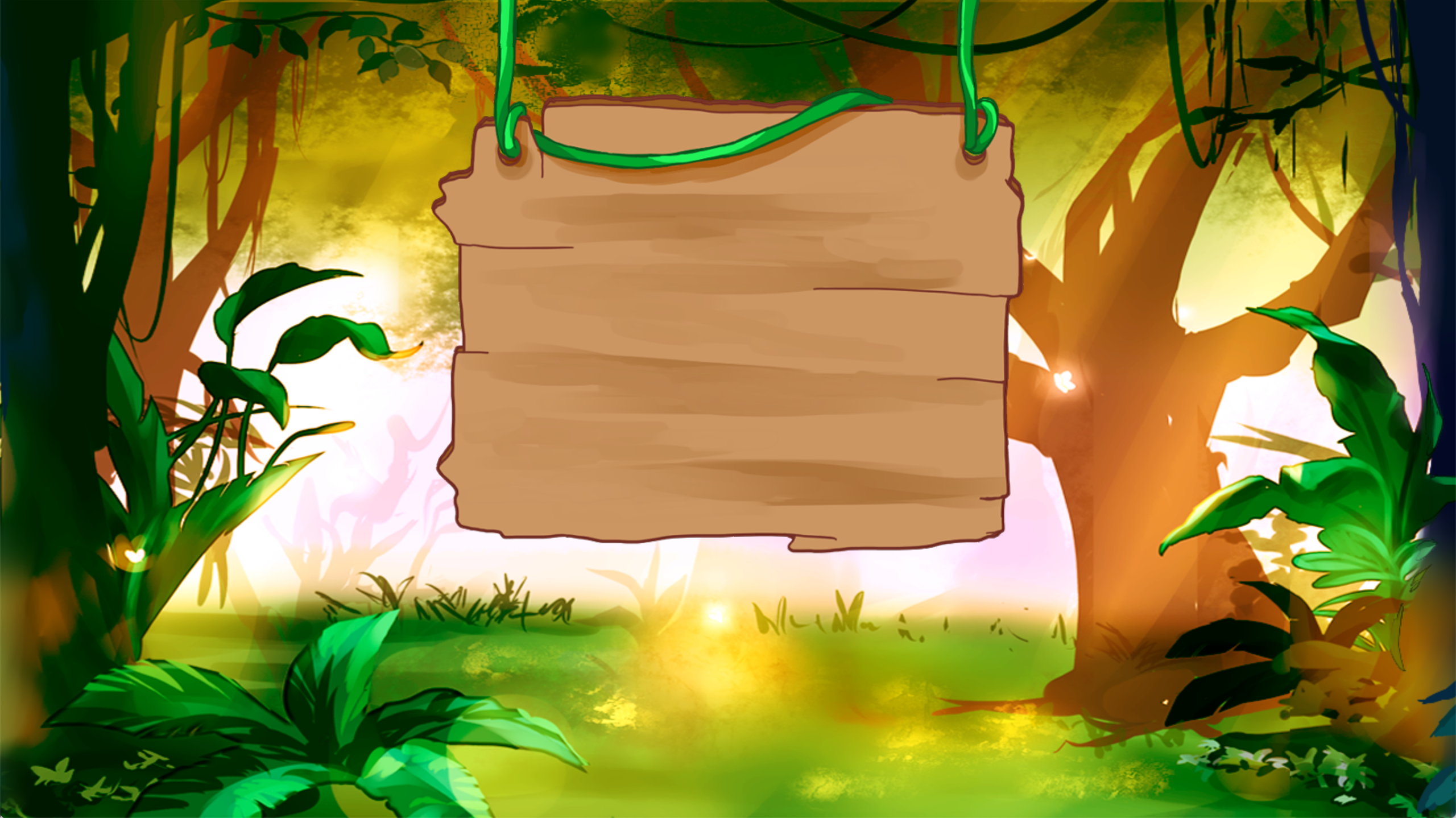
Try this on different aspect ratios. The menu should always remain centered at the top.
At this point you might wonder why we need to set both the anchor and the layout
values to properly anchor a node. That is because the anchor layout is applied
not to the entire node, but to the anchor point. As an example, change your
anchor point of "startmenu" to
"anchor": [0.5,0.5]
Now run the tool. See how the center of the board is anchored at the top? So by combining anchor points with anchor layout positions, you actually have a fair degree of control over your positioning.
We will explore more layout options next week. Before continuing on, you should add
the following to "startmenu".
"format"    : {
    "type" : "Anchored"
}
That is because we are going to start adding children to "startmenu", and we want
it (not just the root scene) to have its own anchor layout.
3. Add Navigation Icons
You are now going to add two navigation icons to the menu. When you are done, the 16x9 version should look like this:

We are going to start with the icon for left navigation. You are going add a new
image to the scene graph (we called it "leftarrow") that uses the left arrow texture
called "left". However, this time the image is a child of "startmenu", not the
root node. So you will need to add a children JSON object to "startmenu". Using
anchor layout, anchor the image to the bottom left corner. When you are done, it
will look like this:
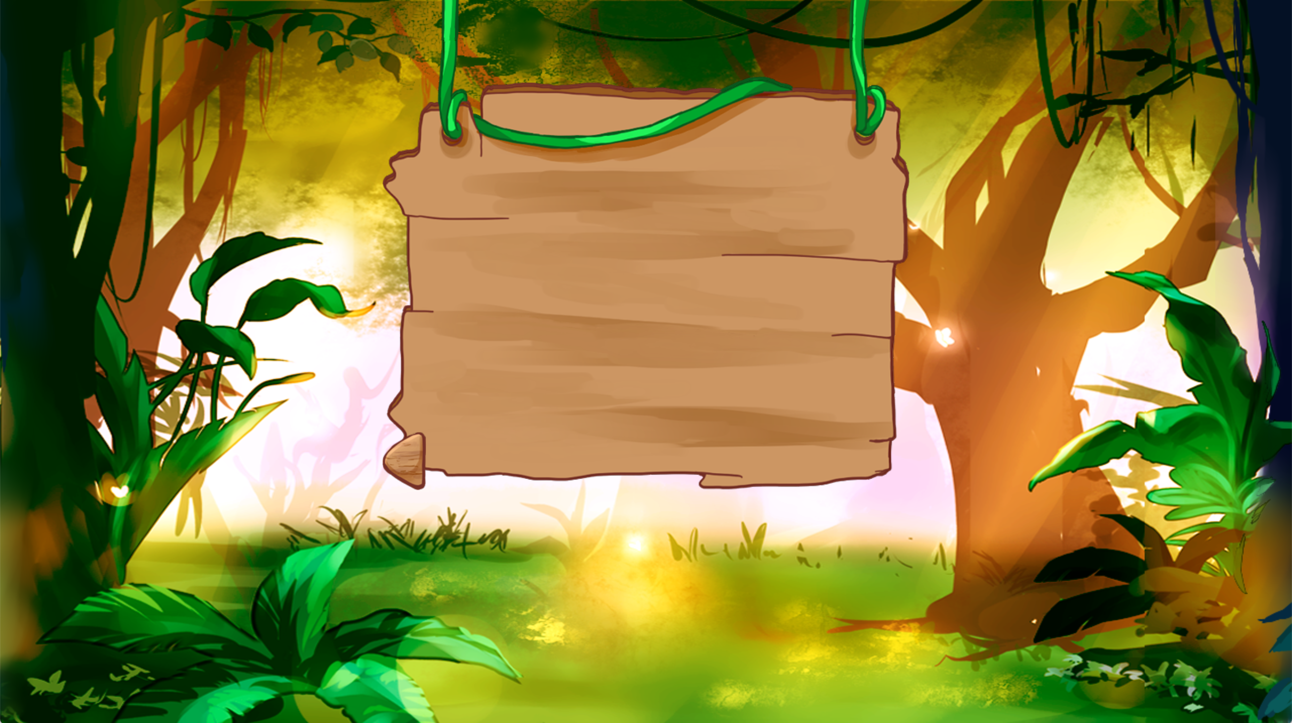
There are a couple of things to notice here. First of all, the bottom left corner refers to the bottom left of the menu, not the screen. That is because the navigation icon is a child of the menu, and not a child of the screen. Understanding this is important for creating interesting UI elements.
The other thing to notice is that the icon does not sit nicely on the board. If you
look at the image file for "left_arrow.png" in the textures folder you will notice
that it has a lot of blank space around the menu board to make room for the uneven edge.
The layout manager does not know anything about transparencies. It places the child
with respect to the rectangle containing the image.
To solve this problem, we need to adjust the left arrow. Fortunately, we can solve this
with layout offsets. Add the following two values to "layout" in your scene graph
node for "left"
"y_offset" : 0.1,
"x_offset" : 0.1
This will nudge the image up by 10% of the size of the parent "startmenu", and to
the right by 10%. When you run the game again, you will see the following:
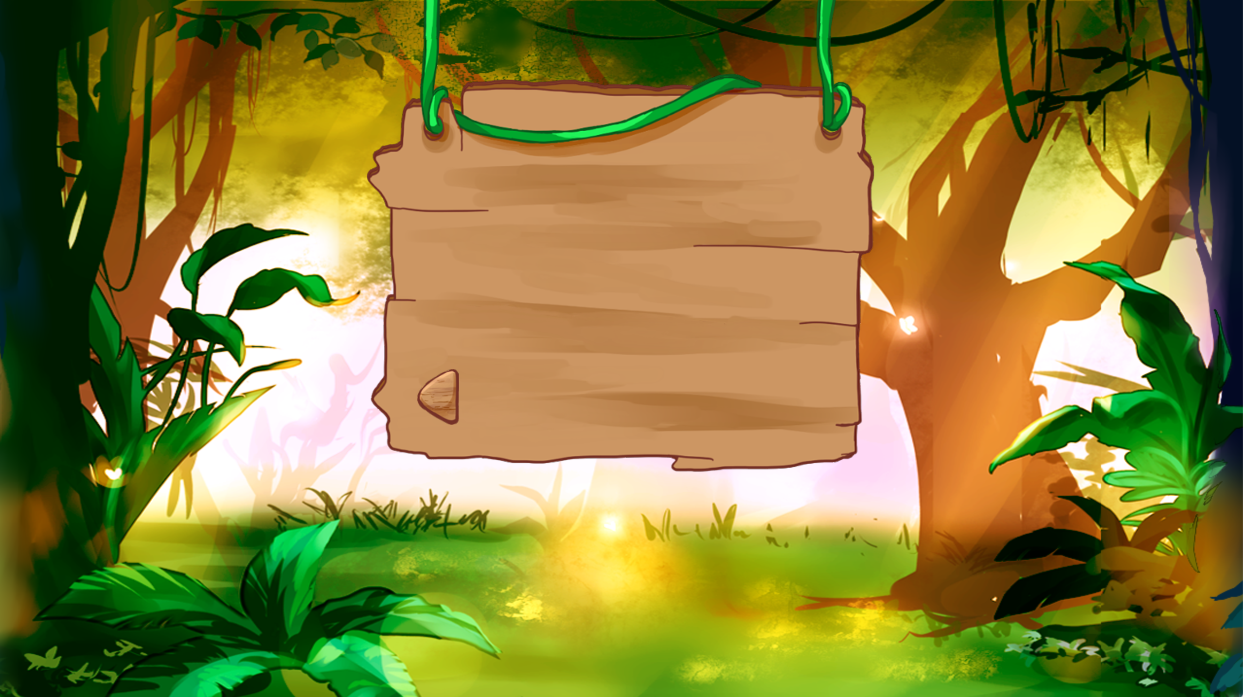
Notice – just like anchors – we always offsets measure in terms of a percentage. While it is possible to express this offset in pixels (see the documentation), percentages are much better for aspect ratio independent design. A value greater than 1 will nudge the child outside of the parents content box. If you need to nudge an image left or down, you would use negative values.
Repeat this process with the texture "right" to add the right arrow. You will need to
nudge this 10% to the left and 10% up. When you do that, you will see the image
that we showed you at the start of this task.
4. Add Navigation Buttons
We have a somewhat interesting scene graph now. However, it is made up entirely of static images. Nothing happens when you click on it. So your next goal is to turn the left and right arrows into buttons. You do not need to write any code to do this. The project that we have given you automatically detects any buttons in your scene graph and activates them. So when you are done, you will be able to click on one of the buttons and have it darken, like in the image below.
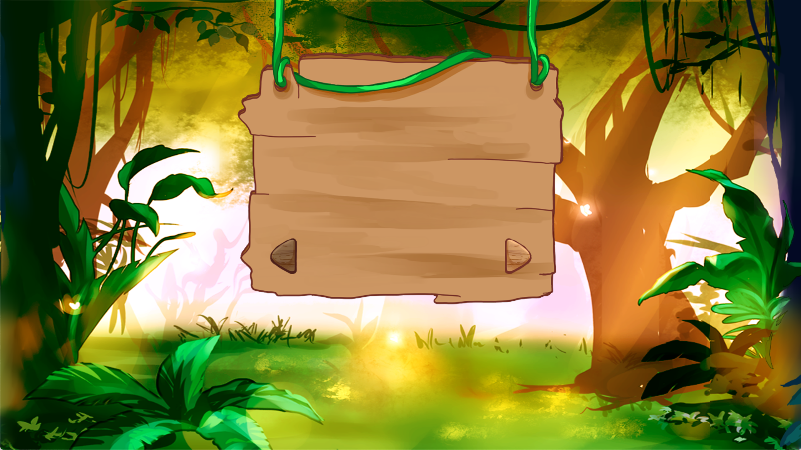
Technically, a button is a scene graph node with two children: an up child and a down child. When the button is up, only the up child is shown. When it is down, only the down child is shown. It is also possible to create a button with only a up child. In that case, the button will darken when you click on it. The is what you will doing in this step.
To make an image into a button, you have to take the image and make it a child of
an node of “type” button. However, with exception of the "texture", all of the data
goes in the button node, not the image node. For example, if you look at "loading.json",
you will see that the play button is roughly specified as follows.
"play"  : {
    "type"   : "Button",
        "data"   : {
            "upnode"   : "up",
            "anchor"   : [0.5,0.5],
            "scale"    : 0.8
        },
        "children" : {
            "up"       : {
                "type"   : "Image",
                "data"   : {
                    "texture"  : "play"
                }
            }
        },
        "layout" : {
            "x_anchor" : "center",
            "y_anchor" : "middle",
        }
We have removed some of the properties like "pushable" as they are advanced features
that are not part of this lab ("pushable" is used to define the clickable region of
non-rectangular buttons). But the key thing to see here is that properties like
anchor and scale are applied to the button, not the image. The only thing the image
specifies is the texture.
There is one important data property that we have not mentioned: "upnode". This value
must be the name of the child that is going to represent the up state. If we had
a child representing down, we would assign that with the property "downnode".
With this in mind, turn both the left arrow and the right arrow in buttons. When you are done, you should be able to click on each of them.
This completes the lab. You will finish this scene next week.
Submission
Due: Fri, Feb 10 at 11:59 PM
After a shorter initial design lab, this one is obviously more work. However, we have still kept the workload light to give you time to learn how scene graphs work (and have also extended the deadline so it is after the scene graph lecture). Next week you will have even more to do, as we will assume that you fully understand scene graphs by then (and you will have had the lecture on the topic).
To turn in the lab, simply submit your final assets.json file to
CMS. We do not need anything else.
