
Input/Output (I/O)
Throughout this semester we have largely focused on the two main components of a Von Neumann architecture: the processor and memory. As we’ve said numerous times throughout the course of the semester, the processor does computations and memory stores data. This simplified presentation, while useful for pedagogical purposes, results in a computer that is frankly, pretty boring. We are lacking any way of providing inputs to our programs, so we are restricted to writing programs that produce the same result each time we run it. Similarly, our programs lack any way of returning any outputs. If we can’t interact with our programs, and they can’t interact with their environment, what is the point of running them at all?
I/O Devices
Real-life computers often have many I/O devices connected to it at any given time. You undoubtedly have a keyboard and mouse connected to your computer, for instance. These two I/O devices enable you, the user (a human), to provide direct input to the computer. You also likely have a microphone and webcam for audio and video inputs. Conversely, the computer might use your display/graphics, speakers, or even a printer to communicate with you, the user/human.
Modern computers also have a number of I/O devices that are used to communicate with other machines. For example, I would be surprised if your laptop didn’t come equipped with a network interface controller (NIC) to connect to the Internet with. You also (very) likely have at least one persistent storage device device, like a hard disk drive (HDD), solid-state drive (SSD), even a USB thumbdrive.
A common misconception is that memory and storage are interchangeable terms. While both refer to technologies that store data, they differ in their speed and volatility. Volatile memory requires power to maintain the stored information, whereas non-volatile (or persistent) storage will retain data without power. Memory generally refers to fast, volatile data storage technologies such as registers and DRAM. Storage, on the other hand, refers to slower, non-volatile (persistent) technologies like HDDs and SSDs.
I/O devices also vary wildly in how fast they can send and receive data. For example, keyboards only need to tell the computer which keys were pressed, so they only send about 100 bits/sec. Mice send about 3,800 bits/sec. Network devices work much faster with a data rate ranging from ~10 megabits/sec. all the way up to 400 gigabits/sec. HDDs are much slower in comparison with a data rate ranging from 800 megabits/sec. to 3 gigabits/sec.
The takeaway here is that while I/O devices come in all different shapes, sizes, and speeds, they enable a computer to interact with its environment and are thus essential for building interesting, useful computer systems.
Interconnects
Now that we’ve established that we need I/O devices, how do we actually integrate them into our computer system? We need some type of interconnect or bus to physically connect our processor and main memory together, in addition to a host of I/O devices. An interconnect consists of two main parts: a physical pathway that facilitates the actual data transfer, and a communication protocol to ensure that the data exchange is orderly. A common way of thinking of an interconnect is as a “data highway”. In this analogy, the physical pathway is the road itself and the communication protocol are all the traffic signs, lights, and pavement markings to prevent collisions and regulate the flow of traffic.
Attempt 1: Unified Memory and I/O Interconnect
As a first attempt, let’s do the simplest thing we can think of: connect the CPU, main memory, and all I/O devices on a single, unified memory and I/O interconnect. Consider the diagram below.
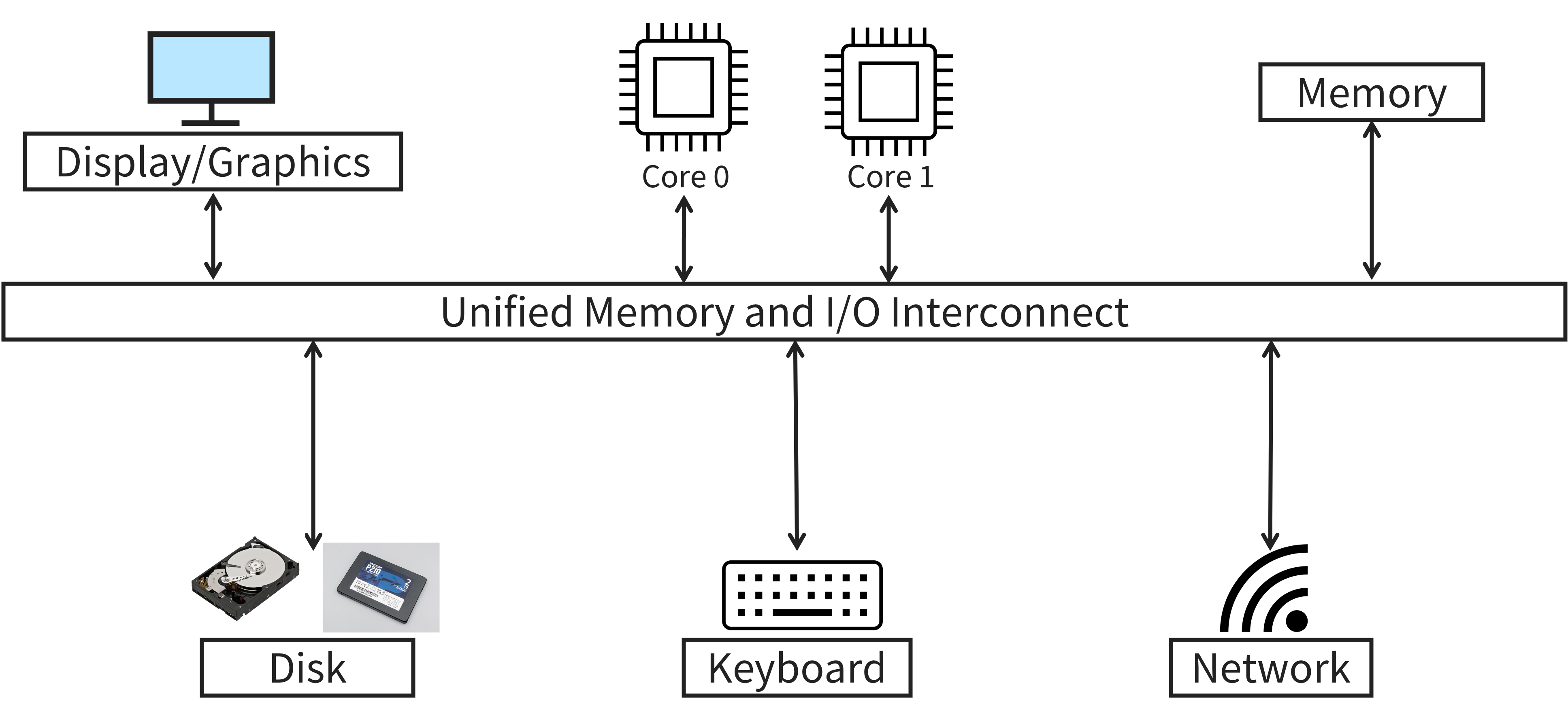
Perhaps unsurprisingly, there are several issues with this design:
-
The CPU is directly responsible for transferring data between devices. For example, suppose we want to read a file stored on an SSD and load its contents into main memory. Currently, the CPU has to communicate with the SSD over the shared interconnect and manually copy the data into main memory. As you might expect, this is time consuming and inefficient for the CPU to do as I/O devices are magnitudes slower than the CPU itself.
-
All devices have shared latency. Since all the devices on the computer are communicating over a shared channel, all communication must happen at the same speed too! Think back to the highway analogy: most highways have a speed limit. It would be rather dangerous to have some vehicles going 100 mph while others go 5 mph1! As a result, the slowest device determines how fast the interconnect can be, meaning that main memory and your keyboard would transfer data at the same rate.
-
If the interconnect were to change (e.g., it broke, desire to upgrade), all devices would need to be replaced. The physical connection interface, the interconnect latency, and/or the communication protocol are all device specific. There is no guarantee that the new interconnect would be backwards compatible with the old interconnect. This is clearly wasteful and undesirable.
Attempt 2: I/O Controllers
One of the key downsides of our first attempt was that our I/O devices were directly connected to the unified interconnect, requiring the CPU to manage each I/O device. Additionally, if the interconnect were to change, we’d need to replace all of the devices with it. Our next iteration introduces a buffer between the I/O devices themselves and the interconnect, called an I/O controller. An updated diagram is shown below.
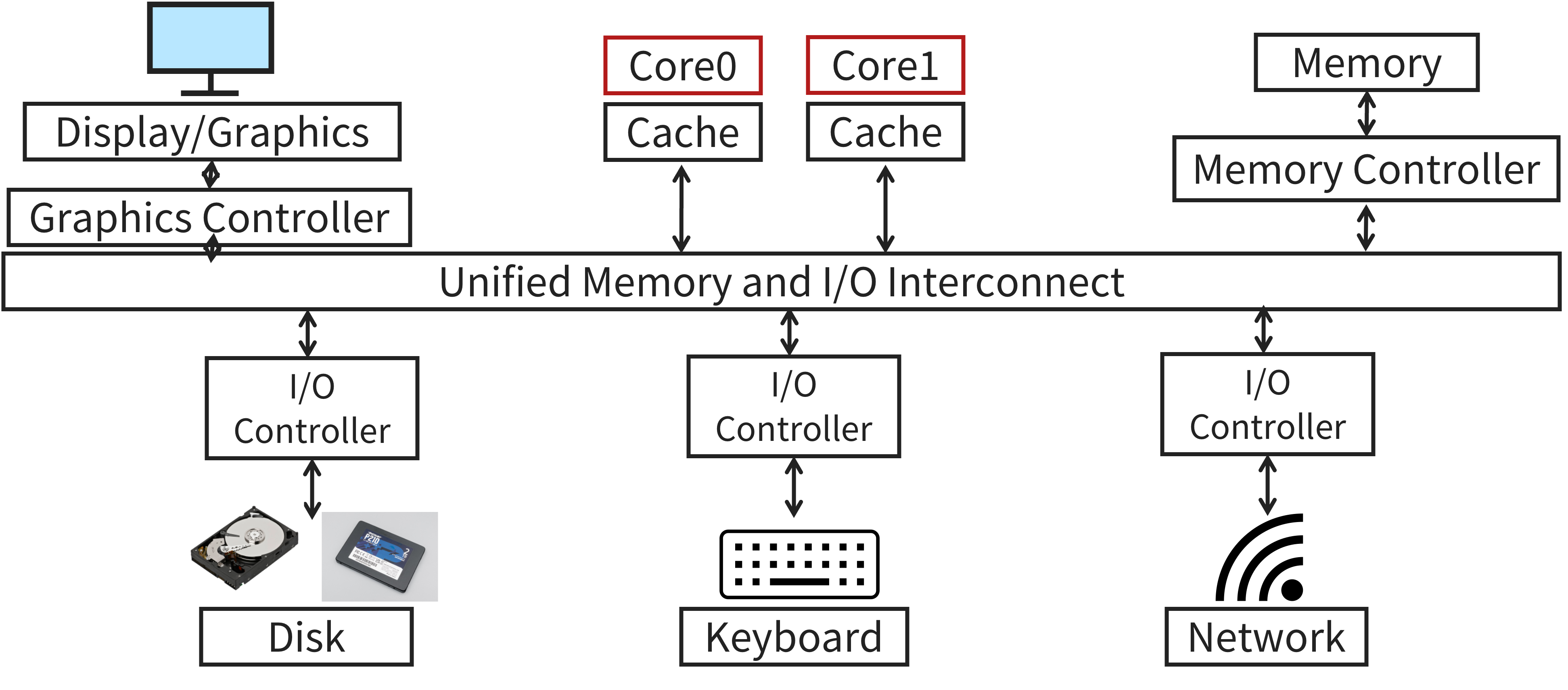
I/O controllers are responsible for managing data transfer between the CPU and the other devices connected to it. This offloads the tedious task of data transfer away from the CPU, freeing it to perform more important, compute intensive jobs. Additionally, we have removed the dependency between the interconnect and the I/O devices. If we had to change the interconnect, we could keep our I/O devices as long as the new I/O controller is compatible. Lastly, these I/O controllers can afford support more device specific features. Before, the CPU would have to know how to interact with each individual I/O device. I/O controllers abstract away many device-specific details from the CPU, decreasing cross-device dependencies. Overall, I/O controllers enable smarter, more efficient I/O interfaces.
Attempt 3: Interconnect Hierarchy
Our second attempt was a step in the right direction, but we still have the issue of shared latency to deal with. Some components, like main memory and graphics, are order of magnitude faster than lower-performance devices like storage drives and keyboards. This observation leads us to our final design, shown below.
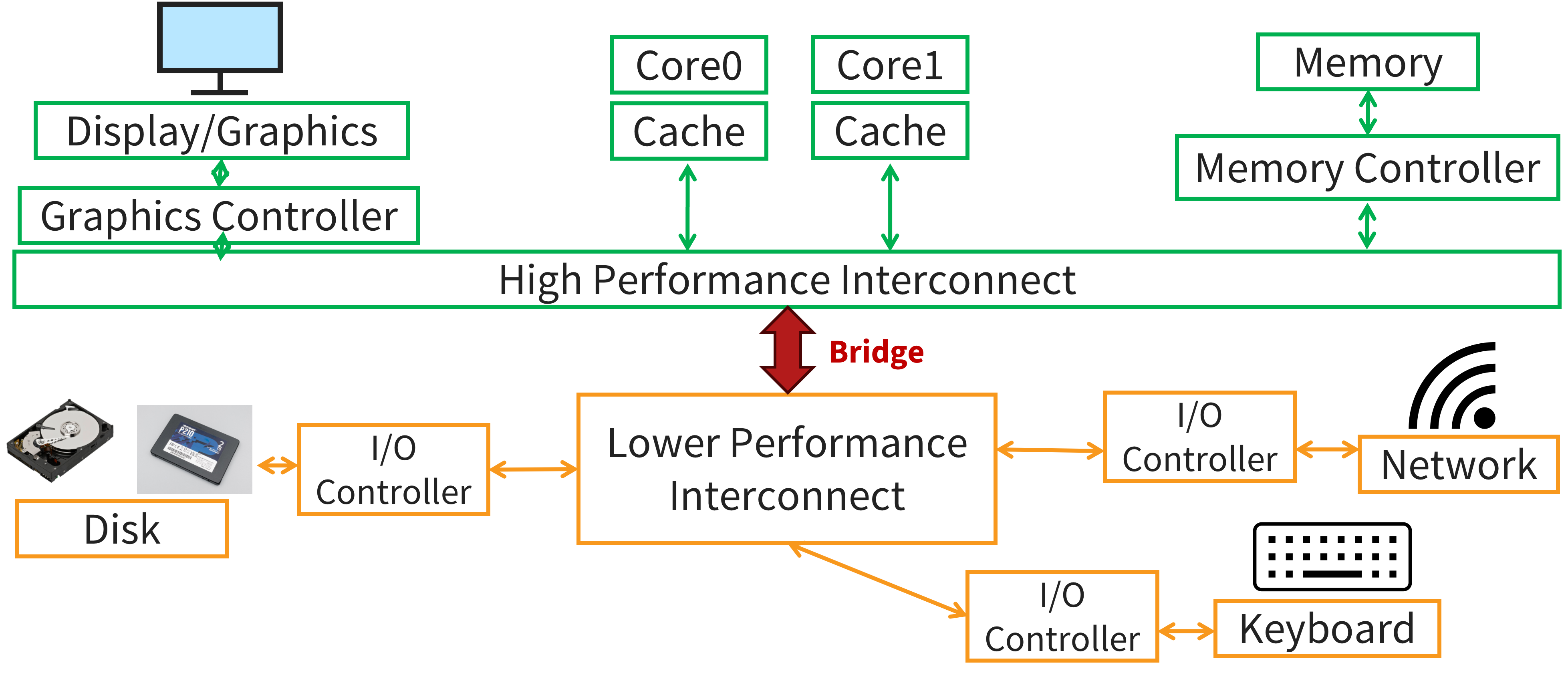
Now we have two interconnects: a high performance interconnect for high performance devices such as the CPU, graphics, and main memory, and a lower performance interconnect which connects all the other, slower I/O devices. Then, we connect these two interconnects together with a bridge. For example, Intel’s proprietary bridge is called the Direct Media Interface (DMI). The processor is still able to communicate with the I/O devices connected to the lower performance interconnect via the bridge without bottlenecking the data transfer rate between the CPU and main memory, for instance.
You might be asking why we need this hierarchical structure like this? The short answer is physics and cost. At the end of the day, the interconnect sends electrons across a piece of metal, which takes time. The shorter the distance the electrons need to travel, the faster the data transfer is. Additionally, engineering a high performance interconnect is quite costly. Therefore, it is desirable to put components that demand high performance nearer to the CPU and lower performance components further away. Another benefit of this construction is that since you can place the slower devices further away from the CPU, you have more space to connect these devices, and so you can connect more of them to a single interconnect.
The high performance interconnect, often called the “front side bus” or the “North side bus”, is short, fast, and wide (think more lanes in a highway). Consequently, the lower performance interconnect, or the “South side bus”, is longer, slower, and narrower. The upside is that they have a more flexible topology to allow for more (and more varied) connections. Not only is this construction more efficient, it is more usable as the dependency between the core of the computer (e.g., the CPU, memory, graphics) from the peripherals (e.g., USB thumbdrive, mouse, keyboard, SSD).
Examples
Recall that an interconnect is more than just a bunch of wires; the communication protocol, or bus protocol, is equally important. Further, as we’ve established, in order to handle the diverse array of I/O devices at our disposal, we need a range of hierarchical interconnects.
Perhaps the most widely known interconnect is the Universal Serial Bus (USB), geared towards connecting a wide range of external peripheral devices. SATA and SCSI are used to connect storage devices. Faster devices, such as NICs, usually use PCIe (Peripheral Component Interconnect Express). Modern SSDs are increasingly use the NVMe specification on top of PCIe to support faster storage devices. Graphics cards also use PCIe, but usually with many more parallel lanes than other PCIe compatible devices like NICs.
Modern datacenters also employ point-to-point (direct) interconnects which connect whole computers together. For example, InfiniBand (primarily used by NVIDIA) has a throughput of up to 2400 gigabit/sec! HyperTransport can be roughly understood as AMD’s variant of InfiniBand.
I/O Device API
The canonical I/O device has two parts: the internals and the interface. Internally, modern I/O devices have a few hardware chips (perhaps even a simple CPU) to implement the abstraction that the device presents to the system. They also typically have a bit of memory. Firmware is the software the runs on these internal chips that implements its functionality.
The second part of all I/O devices is the interface. Typically, there are a set of read-only and/or read/write registers that are split into three categories: the status registers, which can be read to query the status of the device, the command registers, which can be written to tell the device to do something (e.g., write data, perform a self test), and the data registers, which are used to transfer data between the device and the rest of the computer.
For example, the IBM PC/AT’s keyboard has four, one-byte registers: a status register, a command register, an input register, and an output register.
The status register is broken up further into eight flags, each a single bit.
The least significant bit of the status register, for instance, is set to 1 when the output register is full and 0 when it is empty.
This keyboard supports a number of commands, such as performing a self test.
To do this, we just have to write the byte 0xAE to the command register.
Once the test is done, we can read the result from the output register.
Accessing I/O Device Registers
There are two ways of interacting with I/O devices.
The first is called programmed I/O (PIO).
PIO is simple; we have our main CPU execute special instructions to transfer data to/from the I/O device.
The inb/outb system call functions allow us to read/write a single byte from/to a given port.
A port is simply a name for the device register we want to access represented as an integer, defined by the device.
These instructions are usually privileged, meaning the OS is in charge of who gets to access the devices.
Let’s write a function which reads the character that was just pressed using the PIO method.
char read_kbd() {
  char status;
  // Wait until key has been pressed
  do {
    sleep();
    // Read status register
    status = inb(0x64);
  } while (!(status & 2));
  // Return the character that the user entered from the input register
  return inb(0x60);
}
The read_kbd() function returns the character that was most recently entered on the keyboard.
First, the OS waits for a key to be pressed by repeatedly reading the status register and checking whether the IBF flag is set, indicating that the input register is full.
This is called polling.
The second method of interacting with I/O devices is known as memory mapped I/O. This approach makes the I/O device’s registers available as if they were memory locations. To access a particular register, we can either load or store from that memory address. The hardware then routes the load/store to the device instead of main memory.
struct kbd {
  char status, pad[3];
  char data, pad[3];
};

char read_kbd() {
	kbd *k = mmap(...);
  char status;
  do {
    sleep();
    status = k->status;
  } while (!(status & 2));
  return k->data;
}
Notice that the structure of the memory mapped version of read_kdb() is nearly identical to the PIO version.
We still are polling the device to know when a key has been pressed.
However, instead of making explicit calls to inb(), we mmap() the registers into the kbd struct.
Then, to access these registers, we just need to load/store from/to the status and data fields.
The hardware forwards these loads/stores to the I/O device for us.
Memory mapped I/O is popular because it allows us to depict the structure of the I/O device’s interface in software by defining a struct.
With PIO, we not only need these special inb() and outb() system calls, but we also need to know the magic port numbers that correspond to the registers we want.
Memory mapped I/O also allows us to reuse the same load/store instructions we use to access main memory.
Polling vs. Interrupts
Above, we used polling to query the status of the I/O device. While this approach is simple and it works, it feels inefficient as we are putting the CPU to sleep while it waits for data to be ready. It would be great if we could instead have the OS issue a request to the I/O device, put the calling process to sleep, and then context switch to another task while we wait. Luckily, we have already seen the perfect mechanism to implement this behavior: interrupts. Using interrupts, we can have the I/O device inform the CPU when it is done fulfilling a request. Interrupts allow us to perform computation and I/O in parallel.
It is worth noting though that interrupt-based I/O is not always more efficient than polling. If the device is fast, the cost of interrupt handling and context switching may exceed the time spent sleeping in polling. For this reason, interrupts tend to make more sense for slow devices. Many systems use a hybrid approach that polls for a little while and then, if the device hasn’t finished yet, falls back to using interrupts.
Direct Memory Access (DMA)
While interrupts allow us to avoid polling, we still have a pretty glaring inefficiency that we need to handle. Suppose we are using PIO to transfer a large amount of data to the device. Here, the CPU is stuck with the tedious task of copying data from main memory to the device. Ideally, we want our CPU to work on difficult, compute intensive tasks and not mundane ones.
To solve this inefficiency, we introduce Direct Memory Access (DMA). A DMA controller is a specific device whose sole purpose is to transfer data between main memory and I/O devices on behalf of the CPU. The CPU is then free to work on other, more pressing jobs while DMA handles the trivial task of data transfer.
To use DMA, first the CPU sends a DMA request telling the DMA controller where the data lives in memory, how much data to copy, and which device to send it to. Once the request is sent, the CPU is free to work on anything else while the DMA controller works on fulfilling the request. Once completed, the controller raises a hardware interrupt, informing the CPU that the transfer is complete. The key benefit of this approach is that the CPU is no longer stuck being the middle-man between the I/O device and main memory. DMA is the technology that enables memory-mapped I/O.
Cache Coherency & DMA
Unfortunately, DMA can lead to cache coherency problems. Suppose we want to write some data to a storage drive. If the cache is not flushed to main memory before the request is sent, the drive will receive stale data. Similarly, if we read some data from the same storage drive, the cache could become stale. If we don’t invalidate the cache after the DMA controller writes the updated to memory, the CPU will operate on the stale data currently in cache.
There are two solutions: a software-based solution and a hardware-based solution. With software enforced coherence, the OS must flush the cache before an outgoing DMA transfer is started. For incoming DMA transfers, the OS must invalidate the cache lines that are affected by the transfer. The OS could also mark certain pages as “uncacheable” to prevent the issue of cache coherency from cropping up at all! Naturally, all these methods introduces some amount of overhead to each DMA request.
Hardware enforced coherence, or snooping, uses hardware to constantly monitor the transactions between the I/O devices and main memory. When the “snooper” detects a transfer from an I/O device to memory, the snooper invalidates or updates the data in cache. Similarly, the snooper also determines whether to have cache service an outgoing DMA request or RAM, depending on which memory location has the most up-to-date value.
-
A notable exception is the Bundesautobahn (a.k.a., the Autobahn) in Germany which is largely devoid of speed limits. ↩