
Welcome to Logisim! Logisim is a logic simulator that allows you to design and simulate digital circuits using a graphical user interface. Logisim comes with libraries containing basic gates, memory chips, multiplexers and decoders, and other simple components. In later assignments you will use many of these components to build your final CPU. For this lab, we will guide you through the process of creating your first adder in Logisim.
1. Logisim requires Java 5 or later. If you do not already have it on your computer, Java is available from java.sun.com.
2. Download Logisim from CS3410 class webpage or from Logisim SourceForge page. You will have three choices of release to download.
3. To execute the program:
| Show your XOR circuit to your TA. |
Now that you have implemented your first XOR gate in Logisim, let us work on a more complicated circuit -- an 8-bit adder. You may find some of the terms, such as two's complement numbers, are difficult to understand. Don't panic. You will not need to understand it in order to finish this lab. Again, the purpose of lab0 is to get you familiar with the software environment that you will be working in for this class in the next few weeks.
Definition (excerpt from Wikipedia article):
A full adder adds binary numbers and accounts for values carried in as well as out.
A one-bit full adder adds three one-bit numbers, often written as A, B, and Cin;
A and B are the operands, and Cin is a bit carried in (in theory from a past addition).
The full-adder is usually a component in a cascade of adders, which add 8, 16, 32, etc. binary numbers.
In the notation below, A[8] denotes that the input is named "A" and is 8 bits wide. The input should not be named "A[8]". Another incorrect approach is to create eight separate inputs, each named A or some variant. Instead, the correct approach is to create a single input and make it 8 bits wide by changing the "Data Bits" attribute of the input. The attributes appear on the lower left pane of the Logisim window when the input is selected.
| Add8: | C = A + B + Cin; V = overflow |
| Inputs: | A[8], B[8], Cin |
| Outputs: | C[8], V |
The output C is computed by adding A, B, and Cin. A, B, and C are signed two's complement numbers. If overflow occurs, the output V should be asserted. In such cases, the output C should correspond to the value computed if all overflow errors are ignored.
Use sub-circuits to make wiring easier by building a 1-bit adder, then a 4-bit adder, and then an 8-bit adder. Using a sub-circuit in Logisim is equivalent to writing a function and using it multiple times when coding. To create a new circuit, select "Project->Add Circuit..." from the toolbar. To use a circuit (A) as a sub-circuit of another (B), double-click on circuit B on the left pane of Logisim (the Explorer Pane). A magnifying glass appears on circuit B's icon, and now the contents of circuit B appear on the right pane (the Canvas). Click once on circuit A in the Explorer Pane, then click anywhere in the canvas to place an instance of circuit A as a sub-circuit of circuit B. As one would expect, any time circuit A is updated, all instances of it appearing in circuit B will change their operation in the same way.
For more information on sub-circuits, the corresponding documentation pages are useful.
| Inputs | Outputs | |||
|---|---|---|---|---|
| A | B | Cin | Cout | S |
| 0 | 0 | 0 | 0 | 0 |
| 1 | 0 | 0 | ||
| 0 | 1 | 0 | ||
| 1 | 1 | 0 | ||
| 0 | 0 | 1 | ||
| 1 | 0 | 1 | ||
| 0 | 1 | 1 | ||
| 1 | 1 | 1 | ||
| S = A xor B xor Cin |
| Cout = (A and B) or (Cin and (A xor B)) |
A technique called Karnaugh map, named after Maurice Karnaugh, a telecommunciation engineer at Bell labs in 1953, will make the conversion from truth table to boolean algebra very simple. You may peruse the Wikipedia article on Karnaugh maps if you are curious, but this is not necessary at this point.
For now, let us move on to implement the 1-bit adder in Logisim. Create the following circuit in Logisim, then save it as an appropriately-named circuit.
| Show your 1-bit adder circuit to your TA. |
A 4-bit adder is as simple as cascading 4 one-bit adders together, with carry-out from one adder fed into the carry-in of the other adder. Later on in the course, we will discuss why this may not be the fastest implementation (for the interested student: why?), but it will serve our needs just fine for now.
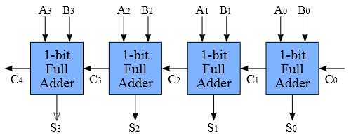
Create the 4-bit adder in Logisim, re-using the 1-bit adder as a sub-circuit.
Ask TA for help if you are unsure of what to do. Save your work in an
appropriately-named circuit.
| Show your 4-bit adder circuit to your TA. |
| Show your 8-bit adder circuit to your TA. |
Now save your work in four steps as a circ file and upload it to the CMS after showing your work to your TA.
Congratulations! You have successfully finished Lab0. Please make sure you have demonstrated your working adder to your TA and upload your circ file to CMS. We will build more circuits with Logisim in the following weeks. For a bit of fun, check out this youtube video to see an example of a cool project created using Logisim.