A1: Enigma
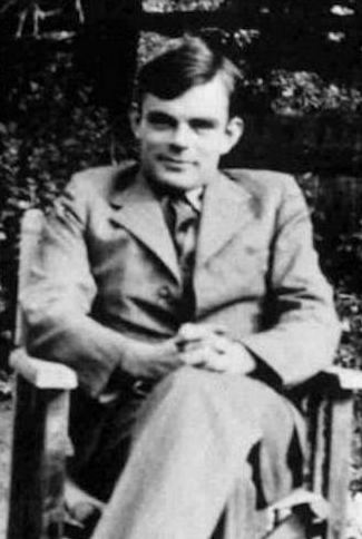
This assignment asks you to develop a software replica of the Enigma encryption machine used by the German military in World War II. Efforts to break the Enigma cipher led to the development of the first electronic computers at Bletchley Park, England. Using computers, the Allies were eventually able to break the Enigma code, giving them an intelligence edge that changed the balance of the war. The most famous of those computers is the Bombe, which was designed by Alan Turing (pictured to the right). Turing is arguably the founder of modern computer science.
This assignment also asks you to work with another programmer, and together to learn about some modern software development tools and methodologies.
What you’ll do: Implement half a dozen functions, and test them with OUnit; maintain your code in Git, a source control tool; and use pair programming and test-driven development, two agile software development techniques.
Objectives:
- Use OCaml data types.
- Model a stateful computation in the functional style.
- Construct an OUnit test suite.
- Become familiar with the basic Git operations of adding, committing, pushing, and pulling.
- Train yourself to write test cases before writing code.
- Experience a disciplined process for in-person coding with another programmer.
Table of contents:
- Getting Started
- Step 1: Pair Programming Tutorial
- Step 2: Get Git Going
- Step 3: Make Sure Make Works
- Step 4: Index
- Step 5: Enigma Tutorial
- Step 6: Rotors
- Step 7: Reflector
- Step 8: Plugboard
- Step 9: Ciphering a character
- Step 10: Stepping
- Step 11: Ciphering a string
- Scope
- Documentation
- Submission
Getting Started
Although the assignment could seem intimidating at first, just take it a step at a time and you’ll do great! The rest of the handout below gives you instructions on each step you should take. There is a series of functions to implement, each of which builds on the ones that came before. By the time you’ve implemented all the functions, you will have finished your Enigma simulator.
The mathematics of the Enigma cipher itself could seem mysterious at first. But we’ve carefully designed the functions to break it down into smaller pieces, so that you can focus on each piece in isolation. We’ve also supplied many examples below that will help you to check your understanding. Developing software in the real world always challenges you to become a little bit of an expert in your client’s domain; think of learning about Enigma as practicing that. As a side benefit, you’ll come away from this assignment understanding an important artifact in the history of computer science.
A highly recommended arts and crafts project: As you proceed with building a simulation of the Enigma machine in this assignment, it could be useful to have a completed simulator at your side. The best Enigma simulator we can recommend is this one. It’s totally worth your while to assemble this simulator. It provides excellent insight into the physical machine, especially the wiring of the rotors and the reflector. To assemble it, you need to buy a tube of Pringles potato chips, print out the paper at 100% scaling (which can be tricky because it’s A4; to help with that we provide these close-ups [1] [2] of the important parts that should be printable on letter paper), then cut out the paper pieces and wrap them around the tube.
Step 1: Pair Programming Tutorial
Pair programming is not just “having an assignment partner;” rather, it’s a specific way for two people to write code together, and for both of them to own the result. Please watch this video, which explains the driver and navigator model of pair programming:
Does that video have you excited about pair programming? Or are you feeling wary? Either way is okay. The purpose of pair programming in this assignment is to expose you to a tool that you can keep in your toolbox and pull out in the future when it feels right. All we ask is that you keep an open mind and give it a try.
If you’d optionally like to read more about the benefits of pair programming, Strengthening the Case for Pair Programming by Williams et al. (2000) is a good place to start. It includes this quote:
For years, programmers in industry have claimed that by working collaboratively, they have produced higher-quality software products in shorter amounts of time. But their evidence was anecdotal and subjective: “It works” or “It feels right.” To validate these claims, we have gathered quantitative evidence showing that pair programming—two programmers working side by side at one computer on the same design, algorithm, code, or test—does indeed improve software quality and reduce time to market. Additionally, student and professional programmers consistently find pair programming more enjoyable than working alone. Yet most who have not tried and tested pair programming reject the idea as a redundant, wasteful use of programming resources: “Why would I put two people on a job that just one can do? I can’t afford to do that!” But we have found, as Larry Constantine wrote, that “Two programmers in tandem is not redundancy; it’s a direct route to greater efficiency and better quality.”
Contact your pair: You have been paired by the instructors with another person in the class. Please make contact with them and arrange a meeting as soon as possible.
Step 2: Get Git Going
If you’d like to watch a video tutorial on Git, here is a good one:
Or, for an interactive tutorial, download and run the latest release of Git-it for your operating system.
Sit down in person with your pair-programming partner. Do the following to start your shared git repository:
-
Each of you independently should login to https://github.coecis.cornell.edu/, which is the Cornell-hosted GitHub site. Login with your Cornell NetID and password. When you create your account, we strongly recommend that you use your Cornell NetID as your username. It will make things much easier. Also, please do use the Cornell GitHub, not the public GitHub (whose URL we deliberately omit).
- From the terminal, each of you should run these commands on your own machine:
  git config --global user.name "Your Name"
  git config --global user.email "your-netid@cornell.edu"
If you get an error message that says
command not found, you don’t have Git installed. The VM already does have it installed, and anyone on Mac should already have it, too. -
One of you (it really doesn’t matter which) should create a new repository, or “repo” for short. On the top right of any GitHub page, click the “+” icon, then select “New repository”. Give the repo a name, perhaps “cs3110-a1”, and change the radio button from Public to Private. A public repo would share your source code with the entire Cornell community, which would violate the Academic Integrity policies of this course. Also check “Initialize this respository with a README”. Then click “Create repository”.
-
On the new repo’s page, double-check: does it say “Private” next to the name of the repo? If not, go to “Settings”, “Danger Zone”, “Make this repository private”, and click “Make private”.
-
Click “Settings”; on the settings page click “Collaborators”, and type your partner’s NetID into the search box. Click “Add collaborator”.
-
Your partner should now click on the GitHub icon on the top left in their browser. They should see the repo you just created listed on the left as a repo to which they have access.
-
Next, on the page for the repo, click “Clone or download”. The box that opens can be set to “Clone with HTTPS” or “Clone with SSH”. Set it to HTTPS. Copy the URL from the box.
-
In your terminal, navigate to whatever directory you want to store the repo in on your local filesystem. Type
git clone URL, replacing URL with the URL you copied from the box. That will download the repo into a directory with the same name that you gave it before. Change into that directory by typingcd DIR, replacing DIR with that name. - Download the starter code for this assignment from CMS. Suppose you save
that in
~/Downloads/a1.zip. Then from your repo directory, issue the following commands to move the files into your repo and clean away the downloaded file:$ mv ~/Downloads/a1.zip . $ unzip a1.zip $ rm a1.zipA common mistake is to use a graphical file browser to copy files. If you do that, you will most likely omit copying some dotfiles: files whose names start with
.and most of the time are hidden from you by graphical tools. The most likely symptom of this mistake will be that VS Code is unable to understand your OUnit test suite. - Continuing in the terminal in that same directory, put the starter code
into source control by running:
$ git add a1 $ git commit -m "Import release code from course website" $ git push - Your partner should now clone the repo on their own machine and verify that the starter code is present in the repo.
Congratulations! You now have a shared repository for this assignment.
Step 3: Make Sure Make Works
Run make check from the folder containing the release code. Double
check that you aren’t getting any warnings about your environment, or
your names or types. The make, make docs, make clean, and
make finalcheck commands are also available, as in A0.
There is also a new makefile target, make build. This command will
build your source files, which are named enigma.ml and enigma_test.ml.
Most text editors, including VS Code, will not automatically rebuild
your code for you when you edit it; you are responsible for building your code
by running a command. (This is different from IDEs like Eclipse.)
Tip: if you ever get errors in VS Code that say something about an “Unbound module”, you probably need to rebuild your code.
Step 4: Index
Now start pair programming. Choose one of you to be the driver and the other to be the navigator. The navigator should now close their computer and put away any distracting devices.
Your goal is to implement the function index : char -> int in the file enigma.ml.
-
The driver should begin by typing
code .from the directory that contains the starter codeenigma.ml. That will open your project directory in VS Code. Then use VS Code’s Explorer to openenigma.ml. Both of you should read the specification comment forindex. -
Then open
enigma_test.mland locate the unit test forindex. Both of you should read it. -
Now talk about
indexand agree on what it is supposed to do. The navigator should suggest an idea for one new unit test for the function. The driver should add that unit test to the suite. Remember, the driver is in charge of the low-level details of writing the code; the navigator is in charge of watching out for higher-level issues. The navigator should never take the keyboard away from the driver. The driver is always free to say “trust me” and continue to code for a couple moments without interruption. Barring that, the navigator should do their best to interject helpful advice, to ask helpful questions, and to problem-solve when compilation errors arise. -
The driver should run
makeand verify that the unit tests forindexare currently failing. That’s good! It means you now have a concrete goal: get those two tests to pass. -
The driver should now implement
index. Hint 1: your solution should need only about one line of code. Hint 2: read the documentation of theChar.codefunction and think about how it could help. -
The driver should run
maketo compile and run the test suite. Make sure that both the tests pass. -
Add any other unit tests that you would like to have in the suite. Make sure all tests pass.
-
Finally, re-run
make checkto double-check that you haven’t changed the names and types of any required functions. Continue to do that after implementing each function below.
Congratulations! You’ve implemented and tested your first function as a pair. The methodology you used is called test-driven development (TDD). You write an automated test or two, and check that those tests fail. Then you write code to make the test(s) pass. Working this way ensure that, by the time you’re done coding, you already have an automated test suite; it’s not just something you write at the end. It also capitalizes on your brain’s desire to be rewarded, because you keep getting the sweet, sweet satisfaction of a test case going from failing to passing. Finally, if you ever happen to break older code as you are writing new code, you will instantly be alerted by your older automated tests suddenly failing.
Now let’s save the work that you did in your repo:
-
Run
git status. You should see thatenigma.mlandenigma_test.mlhave been modified. -
Run
git add enigma.ml enigma_test.mlto add those files to the staging area of work that you want to commit. -
Run
git commit. That will open the Vim editor, in which you can type a commit message. It’s important to get used to using an editor to type commit messages, so that you can write longer and more informative messages, rather than always typing them on the command line with the-moption. Vim is a modal editor. - Press
ito enter insert mode. Now type your multiline commit message using the following format. In fact, feel free to use this exact commit message (assuming it’s accurate).Implement Enigma.index - Replaced release code implementation with our own - Added a test caseWe recommend that the first line of the commit be just a few words, with the first one capitalized. The words should complete the sentence “If you pulled this commit into your own copy of the repo, this commit would…” You’re informing the reader what value they’re getting from your commit. The remaining lines should supply details. You’ll notice that if you type too many characters on the first line, Vim will warn you by changing colors. The reason is that GitHub uses that first line to summarize your commit on the website, and too much text makes it unsuitable as a summary.
-
Press the Escape key, then type
:wq, and press the Enter key. Escape puts Vim into normal mode, the colon moves you to the command-line mode, andwqsays to write the file you are editing to disk (i.e., save it) then quit. Vim will close. - Back at the command line, type
git push. Now the navigator should get their machine back out, pull from the repo, and verify that they have the most recent version of the code.
Congratulations! That was a pretty simple function, but you’ve accomplished so much more, including pair programming and git. Feel free to have a dance party. ┏(・o・)┛♪┗ (・o・) ┓
Step 5: Enigma Tutorial
Either with your partner or separately, please watch this video, which introduces the Enigma machine:
(The video ends abruptly; you can watch the second part here. It explains how the Enigma cipher was broken. You don’t need to understand that to complete the assignment, but it’s fun!)
The Enigma was not just a single machine, but a family of closely related machines. So keep in mind that there might be details that differ from one video to another that you watch online, or even between a video and this writeup.
Substitution ciphers. The Enigma machine implemented a substitution cipher, which encrypts a message by substituting one character for another. Such ciphers go back at least as far as Julius Caesar, who used a simple substitution cipher to encrypt military orders. The Caesar cipher specified that each letter in the alphabet would be encrypted using the letter three positions later in the alphabet. For example, ‘A’ would be encrypted as ‘D’, ‘B’ would be encrypted as ‘E’, ‘C’ would be encrypted as ‘F’, and so on. The code wraps around at the end of the alphabet, so ‘X’, ‘Y’ and ‘Z’ would be encrypted as ‘A’, ‘B’, and ‘C’, respectively. Although the Caesar cipher was effective in its time (when very few people could read at all), its simple pattern of encrypting letters seems pretty obvious today.
The Enigma cipher. The Enigma machine, shown below, implemented a more complex keyed substitution cipher. The key is a secret presumably known only to the message sender and receiver; it defines the mapping between a plaintext letter and a ciphertext letter. For the Caesar cipher, the key amounts to the “rotate by 3” operation. The key for the Enigma cipher involved many aspects of the physical configuration of the machine; we describe these below.
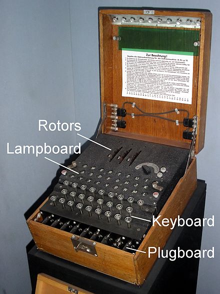
(Click on that image and any of the images below to link to the website where we found the image.)
After the machine was configured with the key, an operator pressed a letter on a typewriter-like keyboard, which caused a circuit to close and light up a letter on a lampboard aka lightboard, a kind of simple display screen. (Note the two different uses of “key” in the previous sentence: the first refers to a cryptographic key, which is a secret used as an input to encryption and decryption algorithms; the second is in the word “keyboard”, which refers to a button that is pressed.) To encrypt a message, the operator typed the plaintext letters, the ciphertext letters would light up, and the operator would record each ciphertext letter on paper. Likewise, to decrypt a message, the operator typed the ciphertext letters, the plaintext letters would light up, and the operator would record each plaintext letter on paper.
Here is a diagram showing more of the internals of the Enigma machine:

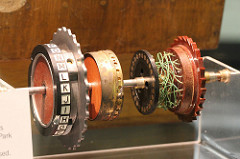
What the diagram calls a wheel is also called a rotor in literature about the Enigma. Henceforth, we will use the term rotor. The rotors were installed next to each other on a spindle, around which they rotated. Here is a picture of three rotors:
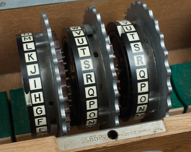
You’ll see the alphabet, in order, on each rotor in that picture. Sometimes rotors were labeled with the alphabet, and sometimes (as in the video linked above) they were instead labeled with the integers 1..26. It makes no difference to the operation of the machine which labeling scheme was used: ‘A’ corresponds to 01, ‘B’ to 02, and so forth.
In the wiring diagram above, there is another disc at the far left of the spindle that looks something like a rotor but in fact does not rotate; it is called the reflector. Here is a picture of a reflector:
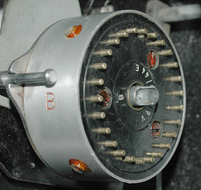
As the diagram shows, when the operator typed a key on the keyboard, electrical current would flow through the plugboard to the rotors, through the reflector, back through the rotors and plugboard, and light up a letter on the lightboard. The reflector, wheels, and plugboard are all mechanisms that could be installed in different ways into the machine. The way in which they all were collectively installed determined the key that was being used for encryption or decryption.
Here is a brief description of each of the mechanisms; we go into greater detail in later parts of this writeup:
-
Each rotor implements its own, distinct substitution cipher by wires that connect the 26 contacts on its left side with the 26 contacts on its right side. The combination of many rotors together on the spindle creates an even more sophisticated substitution cipher. The original Enigma machines used at the beginning of World War II had three rotors, known by the Roman-numeral designations I, II, and III, which could be placed on the spindle in any order. Later, other rotors with different wirings were manufactured, as were machines that could accept up to five rotors on the spindle.
-
The reflector also implements a substitution cipher, though a less sophisticated one. It has 26 contacts only on its right side, but none on its left. Current that it receives from the right side is wired to be reflected back out that side, but in a different position. The reflector was always inserted at the leftmost side of the spindle. A keypress caused current to flow right-to-left through the rotors, through the reflector, then back through the rotors, left-to-right. The reflector’s substitution pattern caused the entire circuit to be symmetric, meaning that if ‘E’ mapped to ‘Q’ in a particular machine state, then ‘Q’ would likewise be mapped to ‘E’ in that same state. The minor advantage of this design was that the machine did not need separate modes of operation for decryption and encryption. But it turned out to be a major cryptographic weakness, enabling the code to be cracked.
-
The plugboard implements yet another substitution cipher, which simply swaps pairs of letters. Though the wiring of the rotors and reflector was pre-determined by how they were manufactured, the wiring of the plugboard could easily be changed by the operator by plugging cables into ports. The plugboard could have up to 13 cables inserted in it. A cable inserted between two letters caused those letters to be swapped. Even though it seems simpler than a rotor, the plugboard was a major source of cryptographic strength for the Enigma cipher.
-
The static wheel shown above is of no interest to us. (It is effectively a no-op.)
What made the Enigma cipher especially difficult to break was that just after the operator typed a letter, and just before that letter was enciphered, the rotors moved, changing the substitution pattern. Thus, the letter ‘E’ might get mapped to a ‘Q’ the first time it was enciphered, but to a completely different letter each successive time. The rightmost rotor stepped for every letter typed, and the other rotors stepped conditionally based on notches on the rotors: when a rotor stepped past a notch, not only did that rotor step, but also the rotor to its left. This stepping mechanism made the rotors work somewhat like a mechanical odometer.
When a rotor was installed, the operator could manually rotate it to be in any of the 26 possible orientations, based on the 26 labels appearing on the rotor (either ‘A’..’Z’ or 01..26). There was a window in the machine through which the operator could observe the top letter showing on each rotor. The letter that would be on top of the rotor at the point in time when the notch engaged was known as the turnover.
(Note: we are omitting one more Enigma mechanism, the ring setting. You can safely ignore it. Aficionados: assume the ring setting is always ‘A’ for each rotor.
The key for the Enigma machine comprises all those physical settings: which rotors were installed, the order they were on the spindle, their initial top letters, and which pairs of letters were connected on the plugboard. An Enigma operator would set all those, then encipher a message. That message would be sent (perhaps by Morse code on a radio channel). The receiver would set their Enigma machine with the same key, type in the received ciphertext, and out would come the plaintext.
Check your understanding: Together with your partner, answer these questions. (There’s no need to turn in your answers to be graded.)
- Define the following terms: plaintext, ciphertext, key.
- Describe the physical design of a rotor. How does it differ from a reflector?
- How many rotors could be installed on the spindle? Were they always installed in the same order?
- How does the plugboard affect the cipher?
- What is the top letter of a rotor? What causes it to change? How often does it change?
Don’t worry if you are not yet 100% solid on how the Enigma cipher works. You now know enough to get started building your simulator, and we’ll fill in the gaps as we proceed.
Step 6: Rotors
Our goal in this step is to implement functions that model how current passes through rotors.
Please note that all the examples and unit tests in this section have been carefully double checked; they do not contain any typos. If you think you’ve found a typo, try to convince your partner. The Pringles-can model is especially good at helping you to debug your understanding. If you’re both convinced, try to convince a consultant.
Rotor wiring. Here is a picture of a disassembled rotor showing some of the internal wiring:
Rather than using complicated diagrams, the wiring of a rotor is often
specified in literature on the Enigma as a 26-character string that is a
permutation of the uppercase letters of the alphabet. For example,
EKMFLGDQVZNTOWYHXUSPAIBRCJ is a wiring specification. Let’s give that
a formal definition:
A valid wiring specification is a 26-character uppercase string that is a permutation of the letters of the alphabet.
A wiring specification has nothing to do with the order in which letters are printed on the exterior of the rotor. (Indeed, you will note that all the pictures above show the letters in alphabetical order.) Rather, the specification describes the interior wiring.
To understand a wiring specification, first forget about the letters. They are
really just shorthand for a number—specifically, the index of that letter
in the alphabet. So wiring specification EKMFLGDQVZNTOWYHXUSPAIBRCJ is better
understood as the following list of numbers: 4, 10, 12, 5, 11, … (Now
you know why we had you implement index.)
Next, let’s associate each of those numbers with its index in the list:
| index in list | index in alphabet |
|---|---|
| 0 | 4 |
| 1 | 10 |
| 2 | 12 |
| 3 | 5 |
| 4 | 11 |
| … | … |
Finally, think of that table as defining a function \(w\), such that \(w(0) = 4\), \(w(1) = 10\), \(w(2) = 12\), \(w(3) = 5\), \(w(4) = 11\), etc.
The function \(w\) we have thus constructed is what the wiring specification really denotes. A rotor has a left side and a right side, and each side has 26 contacts from which electrical current can enter or leave the rotor. If current enters the rotor from the right side at contact \(i\), it leaves the rotor from the left side at contact \(w(i)\). And if current enters the rotor from the left side at contact \(j\), it leaves the rotor from the right side at contact \(w^{-1}(j)\), where \(w^{-1}\) denotes the inverse of \(w\).
Rotor orientation. There are 26 fixed positions at which current can enter a rotor. (For example, if the plugboard is empty, typing ‘A’ causes current to enter the right-most rotor at position 0, ‘B’ at 1, etc.) But current entering at position \(i\) does not necessarily connect with contact \(i\) on the rotor, because rotors turn around the spindle. That rotation causes an offset between the positions and the contacts.
Recall that the operator can see on the top of the machine, for each rotor, one of the letters that appears as exterior label on the rotor. Also recall that those letters are printed on the rotor in alphabetical order. So the offset of the rotor can be can be determined by looking at the letter that is showing. We call that the top letter of the rotor. Here, for example, is a closeup of a three-rotor Enigma machine in which the top letters are currently RDK:
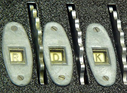
When a rotor is in its default orientation, with ‘A’ showing as the top letter, the offset of the rotor is 0: current entering at position 0 touches contact 0, position 1 touches contact 1, and so forth. But when ‘B’ is showing as the top letter, the offset of the rotor is 1: current entering from at position 0 touches contact 1, position 1 touches contact 2, and so forth.
Likewise, as current exits from a contact on the opposite side of the rotor, that contact is offset from the actual exit position. For example, when the offset is 1, current flowing to contact 1 exits at position 0, contact 2 exits at position 1, and so forth.
Note that the way the offset works is thus independent of the direction that current is flowing—which makes sense, as the offset is determined by the movement of the rotor around the spindle, not by the flow of current through the rotor.
Examples. Now that we know about how wiring and orientation affect how current flows through a rotor, let’s look at some examples. Here is where a 3D model is worth a million words: the Pringles-can model linked above makes these examples considerably easier to follow. Please note that these examples have been carefully checked to ensure there are no typos. If you think you’ve found a typo, try to convince your partner. If you’re both convinced, try to convince a consultant.
Example 1. Suppose the rotor has wiring specification
EKMFLGDQVZNTOWYHXUSPAIBRCJ, its top letter is ‘A’, current is flowing from
right to left, and current enters at position 0:
-
Current entering at right-hand position 0 flows to right-hand contact 0 of the rotor, because the rotor’s offset is 0.
-
Current entering right-hand contact 0 flows to left-hand contact 4, because \(w(0) = 4\) for this rotor’s wiring specification.
-
Current exiting left-hand contact 4 flows to left-hand position 4, because the rotor’s offset is 0.
Example 2. But now suppose that the rotor’s top letter is ‘B’. How would Example 1 change?
-
Current entering at right-hand position 0 flows to contact 1 of the rotor, because the rotor’s offset is now 1.
-
Current entering right-hand contact 1 flows to left-hand contact 10, because \(w(1) = 10\).
-
Current exiting left-hand contact 10 flows to left-hand position 9, because the rotor’s offset is 1.
Example 3. Now let’s redo Example 1, but with current flowing from left to right.
-
Current entering at left-hand position 0 flows to left-hand contact 0 of the rotor, because the rotor’s offset is 0.
-
Current entering left-hand contact 0 flows to right-hand contact 20, because \(w^{-1}(0) = 20\) for this rotor’s wiring specification. (That’s a fact we haven’t previously established, but you should be able to work it out yourself from the fact that ‘A’, whose index in the alphabet is 0, appears at position 20 in the wiring specification.)
-
Current exiting right-hand contact 20 flows to right-hand position 20, because the rotor’s offset is 0.
Example 4. Finally let’s redo Example 2, but with current flowing from left to right.
-
Current entering at left-hand position 0 flows to left-hand contact 1 of the rotor, because the rotor’s offset is 1.
-
Current entering left-hand contact 1 flows to right-hand contact 22, because \(w^{-1}(1) = 22\) for this rotor’s wiring specification.
-
Current exiting right-hand contact 22 flows to right-hand position 21, because the rotor’s offset is 1.
It’s time to write some code.
Complete the functions map_r_to_l and map_l_to_r in the starter code.
Note that these functions do not perform any stepping of the rotor;
rather, they model how current passes through the rotor when it’s in a
particular orientation. We’ll implement stepping later.
Use pair programming and test-driven development to implement these functions.
Begin by implementing map_r_to_l. Here is a suggested workflow:
-
Start by adding this very simple test: The wiring specification
ABCDEFGHIJKLMNOPQRSTUVWXYZwith top letter ‘A’ should cause current to flow from position 0 to position 0. Program a unit test, and verify that it fails. -
Now discuss the algorithm that you together want to implement. Note that for this special wiring specification, you actually don’t have to implement anything to account for orientation. So don’t bother with that part of the algorithm yet.
-
Having sketched out the algorithm (verbally, on paper, on a white board, etc.), the driver should implement it while the navigator supports. Hint 1: take a look at the
getandindexfunctions in theStringmodule. Hint 2: use your ownindexfunction that you implemented above.
- Verify that the unit test passes.
Now repeat that workflow for these progressively harder unit tests:
-
Example 1 above. You still don’t have to account for orientation. If your algorithm is correct, this will pass already.
-
The wiring specification
BACDEFGHIJKLMNOPQRSTUVWXYZwith top letters ‘A’, ‘B’, and ‘C’. That will at last require you to implement code to handle orientation. Hint: You will probably want to implement a modulo operator that differs from the built-in operatormodby always producing a positive remainder. -
Example 2 above. If your algorithms are correct, this will pass already.
Finally, switch roles: the driver becomes the navigator, and the
navigator becomes the driver. Then develop map_l_to_r using the same
workflow as before, but with Examples 3 and 4. Hint: You might want to implement a
function that is the inverse of your index function.
Ideas for more unit tests. Finally, add some even harder unit tests. For example, here are the wiring specifications for the three standard rotors used by the 1930 Enigma I:
rotor I:   EKMFLGDQVZNTOWYHXUSPAIBRCJ
rotor II:  AJDKSIRUXBLHWTMCQGZNPYFVOE
rotor III: BDFHJLCPRTXVZNYEIWGAKMUSQO
You’ll recognize rotor I as the rotor we have used in our examples above. As test cases with those, you could try the following:
-
If
rotor_III = "BDFHJLCPRTXVZNYEIWGAKMUSQO", thenmap_r_to_l rotor_III 'O' 14should be17. -
If
rotor_I = "EKMFLGDQVZNTOWYHXUSPAIBRCJ", thenmap_l_to_r rotor_I 'F' 10should be14.
Note: To head off any potential confusion, be aware that rotors I, II and III are not the only possible rotors. We will test your solution with historical rotors and shiny new rotors. Also, please note that the Roman numerals are the names of the rotors, not the order they are installed on the spindle. Indeed, they could be installed in any order.
Great work! You’ve now implemented a simulation of Enigma rotors.
Finish up by running make check, then committing and pushing
your code to your repo.
This is the stopping point for a satisfactory solution.
Step 7: Reflector
Reflectors are a lot like rotors. Reflector wiring is specified with the same kind of 26-character string as a rotor, and that string is used to define a function \(w\) as before: when current enters a reflector at input position \(i\), it exits at output position \(w(i)\). But reflectors must satisfy one additional property:
A valid reflector specification must be a valid wiring specification, and it also must hold that if \(w(i) = j\) then \(w(j) = i\).
It is this property that makes the wiring a reflection, in the sense that it swaps \(i\) and \(j\).
Beyond that property, reflectors are actually simpler than rotors. Unlike rotors, the reflector does not rotate, so we don’t have to worry about the orientation or offset of the reflector. Also, current flows only one direction through a reflector, so we don’t have to worry about right-to-left vs. left-to-right.
Use pair programming and test-driven development to complete the
function map_refl in the release code. Make sure to keep switching
the driver and navigator roles; and to keep writing failing unit tests
first, then implementing code to make those tests pass. As a first unit
test, try ABCDEFGHIJKLMNOPQRSTUVWXYZ, which it turns out is a valid
reflector specification. Hint: you can implement map_refl in just
one line by using map_r_to_l as a helper.
After that, here are the wiring specifications of the standard reflectors B and C from the 1930 Enigma I:
reflector B: YRUHQSLDPXNGOKMIEBFZCWVJAT
reflector C: FVPJIAOYEDRZXWGCTKUQSBNMHL
Use those to write more unit tests, which if all goes well will already pass.
Note: To head off any potential confusion, be aware that reflectors B and C are not the only possible reflectors. We will test your solution with historical reflectors and shiny new reflectors.
Finish up by running make check, then committing and pushing
your code to your repo.
Step 8: Plugboard
The plugboard swaps pairs of letters before and after current passes through the
rest of the machine. The operator configured the plugboard by inserting cables
between pairs of letters. We’ll represent a plugboard by a list of pairs of
characters. For example, here’s a plugboard in which two cables have been
inserted; one between ‘A’ and ‘Z’, the other between ‘X’ and ‘Y’: [('A','Z');
('X','Y')]. The order of characters in the pairs should not matter and the
order of pairs in the list should not matter. So that plugboard has an effect
that is equivalent to this one: [('Y','X'); ('Z','A')].
A valid plugboard is a list of pairs of characters in which only the letters ‘A’..’Z’ appear, and no letter appears more than once.
A valid plugboard therefore may have anywhere from 0 to 13 elements in
its list. The plugboard with no cables inserted would be represented by
the empty list, [].
Complete the function map_plug, continuing to use pair programming
and test-driven development. The empty plugboard would be a good
first test case, followed by a plugboard with one cable inserted.
Hint: write a recursive function that pattern-matches against the input list.
After that, the two equivalent plugboards above would be good as a basis for several unit tests. Those tests could make sure that the two plugboards do indeed behave the same. Then you could try a plugboard with 13 cables inserted.
Finish up by running make check, then committing and pushing
your code to your repo.
Step 9: Ciphering a character
As before, all the examples and unit tests in this section have been carefully double checked; they do not contain any typos.
Now it’s time to assemble all the functions you’ve written and tested. We’ll first implement the ciphering of just a single character based on the current configuration of the Enigma machine, including the plugboard, the reflector, and the rotors and their orientations. But for now, we continue to leave out any stepping of the rotors.
The cipher algorithm:
-
The operator types a letter \(X\) as input. The design of Enigma limits it to the uppercase letters ‘A’..’Z’. Lowercase letters, numerals, punctuation, spaces, etc. are not supported.
-
(The machine would now step. But we omit stepping for now. We’ll come back to it in a later part of the assignment.)
-
The input letter \(X\) is potentially transformed to a different letter \(Y\) because of the plugboard. The result of that transformation becomes an electrical current at position \(p\), where \(p\) is the index of \(Y\) in the alphabet.
-
That current passes through the rotors, the reflector, and back through the rotors.
At each of those, the output position from one rotor becomes the input position to the next. Eventually current exits the rotors at position \(q\). -
Let \(Z\) be the letter whose index in the alphabet is \(q\). The plugboard potentially transforms \(Z\) into an output letter \(W\), which is the letter that lights up on the lampboard.
An example: Consider the following configuration: reflector B is installed; rotors I, II, and III are installed in that order from left to right; the top letter of every rotor is ‘A’; and the plugboard is empty. Then input letter ‘G’ would be enciphered to output letter ‘P’, as follows:
-
The input letter is ‘G’. The plugboard is empty, so no transformation occurs. Current begins flowing into the rotors at the position of the index of ‘G’, which is 6.
-
Rotor III with top letter ‘A’ maps current from right-hand position 6 to left-hand position 2.
-
Rotor II with top letter ‘A’ maps current from right-hand position 2 to left-hand position 3.
-
Rotor I with top letter ‘A’ maps current from right-hand position 3 to left-hand position 5.
-
Reflector B maps current from position 5 to position 18.
-
Rotor I with top letter ‘A’ maps current from left-hand position 18 to right-hand position 18.
-
Rotor II with top letter ‘A’ maps current from left-hand position 18 to right-hand position 4.
-
Rotor III with top letter ‘A’ maps current from left-hand position 4 to right-hand position 15.
-
Current flows out of the rotors at position 15, which is the index of ‘P’. The plugboard is empty, so no transformation occurs. The output letter is ‘P’.
Expanding on that example, the following table shows how any individual character would be enciphered in that machine configuration. You’ll see, for example, that input letter ‘G’ lines up with output letter ‘P’, as we just explained in detail:
input letter:  ABCDEFGHIJKLMNOPQRSTUVWXYZ
                     |
                     V
output letter: UEJOBTPZWCNSRKDGVMLFAQIYXH
Data types.
The release code defines a config type to represent the
configuration of the Enigma machine: the reflector, the rotors that
are installed and the order they are on the spindle, and the top letter
of each rotor.
A valid configuration is a configuration in which all the wiring specifications are valid, the plugboard is valid, and the turnovers and top letters are all in ‘A’..’Z’.
Note that there might be any number of rotors in a valid configuration: perhaps 0, perhaps the standard 3, perhaps more. And the rotors need not be distinct; there could be duplicates.
Here are a couple notes on the config type:
-
The
reflfield is the wiring specification of the reflector. -
The field named
turnoverin therotortype won’t actually be used in any meaningful way in this part of the assignment; you can ignore it or just set it to an arbitrary letter for now. -
The order of elements in the
rotorslist in theconfigtype represents the order in which the rotors are installed on the spindle, from left to right. For example, if there are two rotors installed, and if the left-most rotor on the spindle (i.e., the rotor next to the reflector) isr, and if the right-most rotor on the spindle (i.e., the rotor next to the static wheel) isq, then that configuration would be represented by the list[r; q].
Function to implement.
Complete the function cipher_char that computes how the Enigma machine
ciphers a single letter. Note that this function still does not perform
any stepping of the rotors; rather, it models how the machine transforms
an input letter into an output letter when all the rotors are in a
particular orientation.
Continue to use pair programming and test-driven development. Here are some ideas for unit tests:
-
When the plugboard is empty, the list of rotors is empty, and the reflector is wired as
ABCDEFGHIJKLMNOPQRSTUVWXYZ, thencipher_charwill behave like the identity function: ‘A’ ciphers to ‘A, ‘B’ to ‘B’, etc. -
The example worked above gives you many possible test cases.
-
Using the Pringles-can model, or simply pencil and paper, you could work out many more test cases yourself.
Hint: consider writing two helper functions,
map_rotors_r_to_l : oriented_rotor list -> int -> int
map_rotors_l_to_r : oriented_rotor list -> int -> int
which compute the output position that results when current enters and passes through an entire list of rotors. They will be recursive functions over the list. Can you factor out a common helper function from them so that there isn’t any duplicated code?
Caution: Something confusing will happen if you attempt to use an
online Enigma simulator to construct test cases for your cipher_char.
Those simulators implement stepping, but cipher_char omits it.
So you might have to use different top letters to get the results you
expect with those simulators. For the details, you’ll have to keep
reading.
Finish up by running make check, then committing and pushing
your code to your repo.
Well done! You’ve accomplished a lot. Give yourself some time to recharge. Have you done anything from this list?
This is the stopping point for a good solution.
Step 10: Stepping
The intuition of stepping is that the rotors behave mostly like the numbers on an odometer: the rightmost completes a full revolution, and in so doing, causes the next rotor to its left to take a single step, and so forth. But the stepping system on the Enigma is a little more complicated. Recall that each rotor has a turnover, which is the top letter that is showing when a notch is reached in the rotor. Those notches cause the rotors to step according to the following rules:
Rule 1: Just before each letter is enciphered, the rightmost rotor always steps.
Rule 2: Just before each letter is enciphered, if the top letter of any rotor is its turnover, then that rotor and the rotor to its left step. This rule does not apply to the leftmost rotor, however, since it has no rotor to its left.
Rule 3: No rotor steps more than once per letter enciphered, even if the above rules could be construed as suggesting that a rotor would step twice.
Some Enigma machines or rotors were built with different stepping rules; in case of discrepancy, the rules above are in effect for this assignment.
Here are the turnovers of some of the historical rotors:
turnover of I:   Q
turnover of II:  E
turnover of III: V
Example 1. Suppose the installed rotors are III-II-I (as always, leftmost to rightmost), starting in orientations where the top letters are KDO. Then as each character is enciphered, they would step as follows: KDO, KDP, KDQ, KER, LFS, LFT, LFU, …
Example 2. Suppose the installed rotors are III-II-I, starting with top letters VDP. Then as each character is enciphered, they would step as follows: VDP, VDQ, VER, WFS, WFT, …
There are no typos in those examples. Really. ☺
Function to implement.
Complete the function step, which computes how the Enigma machine steps just
before enciphering a letter. Its type config -> config is worth considering:
instead of mutating state, we produce a new value out of an old one.
This is a hallmark of the functional style of programming.
This function is the most algorithmically complex part of the assignment. For unit tests, first implement just rule 1; you should have no trouble inventing some tests for that. Then add in rules 2 and 3, using the examples we supplied above as unit tests.
Continue to use pair programming and test-driven development.
Finish up by running make check, then committing and pushing
your code to your repo.
Step 11: Ciphering a string
At last, it’s time to encipher an entire string. The order of operations as they occur on the Enigma machine is as follows:
- The operator types a letter.
- The machine immediately steps to a new configuration.
- The letter is enciphered according to that new configuration.
- The enciphered letter is lit on the lampboard.
- The operator repeats until finished.
Complete the function cipher, which computes how the Enigma machine ciphers a string.
Continue to use pair programming and test-driven development.
It is up to you to invent test cases for this function. There are many online simulators that could help you, such as this one or this one. We don’t know of any that allow arbitrary rotor wirings or numbers of rotors, though. Just do your best!
Actually, here is one test case for you: use reflector B, rotors I, II, and III (from left to right, as always), with starting top letters F, U, and N, and a plugboard with a single cable connecting ‘A’ and ‘Z’. Encipher YNGXQ; it should produce the name of a pretty good programming language.
Finish up by running make check, then committing and pushing
your code to your repo.
YAAAAAAAY! All done!
Scope
Here’s what we consider a satisfactory, good, and excellent solution:
-
Satisfactory: The solution passes
make check. All the functions up through and includingmap_r_to_landmap_l_to_rare completed. -
Good: All the functions up through and including
cipher_charare completed. -
Excellent: All the functions are completed.
Documentation
This assignment is unusual in that the starter code provided functions that were already documented. So when the graders assess your documentation, they will primarily be looking at the documentation of any helper functions you might have introduced. You are free to improve any of the provided documentation, if you wish.
Submission
Set the hours_worked variable at the end of enigma.ml to a list containing
the number of person-hours each person spent working on this assignment.
For example, if you both did the entire assignment at the same computer the
whole time, never working apart, and it took 9 hours, you would report
[9;9]. Order is irrelevant.
Ensure that your solution passes make finalcheck. Submit your enigma.ml
and enigma_test.ml on CMS. Double-check before the deadline
that you have submitted the intended versions of your files.
Congratulations! You’ve solved the Enigma!
Acknowledgement: Adapted from Prof. David Reed (Creighton University).