This tutorial will introduce you to using the Canvas3D commands. The attempt is to get you started with using Canvas3D, and expectations are that you will use all your imagination to make use of the available facilities and create interesting three-dimensional and virtual reality applications! Initially, there is a step by step explanation of the commands for some sample creations. Some other demo examples are given latter on with fewer explanations. Have fun!
Canvas3D : Tests - There are three test files currently available with the downloadable zipped code of Canvas3D. Click here to see the different views and their corresponding source code for the different tests. You may execute these tests (after the installation, of course!) using the Tcl command source, for e.g. % source test1.txt will execute the first test.
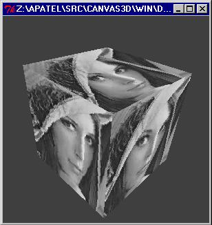
Goal : To create a simple box with lena.ppm image as texture on all its sides. To view this box from different angles.
Step 1 : Every time you wish to start with Canvas3D, run the wish3d executable. This starts an interactive Tk shell with extended Canvas3D support. Other than using all the features of Tcl/Tk, what we want is to start Canvas3D. So enter the commands :
% canvas3d .c -height 300 -width 300
% pack .c
The first command does all the initialization for you. It puts up a black colored window of the specified size ( 300 x 300 in our case ). Well, you can always forget to specify the size, and then you will get a default sized window. The second command is the Tk geometry packer, which makes intelligent decisions to adjust all the Tk widgets socially. Refer the Tcl/Tk manuals for understanding more on the geometry packer.
Note : If you are writing a script file, please add the Tk command update after these two commands to make sure that the initialization is over, before you proceed further.
Step 2 : Now comes a slightly bad part, but you will learn to live with it, since you never need to use these commands again! We want to make our presence existent in the huge coordinate world. So we need to specify the initial position of where we are and what we want to see. Our attempts are currently underway to simplify this as much as possible, but till then, just cut'n'paste these lines :
% set mat1 [ .c create matrix -value {{1.0 0.0 0.0 0.0} {0.0 1.0 0.0 0.0} {0.0 0.0 1.0 1.0} {0.0 0.0 -2.0 0.0}} ]
% set mat2 [ .c create matrix -value {{1.0 0.0 0.0 0.0} {0.0 1.0 0.0 0.0} {0.0 0.0 1.0 0.0} {0.0 0.0 0.0 1.0}} ]
% set mat3 [ .c create matrix -value {{1.0 0.0 0.0 0.0} {0.0 1.0 0.0 0.0} {0.0 0.0 1.0 0.0} {0.0 0.0 20.0 1.0}} ]
% set back [ .c create surface ]
% set view [ .c create viewport -proj $mat1 -world $mat2 -view $mat3 -background $back ]
Let's understand what we did here. We created the projection, window and the view matrices. Using this matrices, we created our viewport through which we can see into the coordinate world. The frustum, position, normal and the up directions of the camera are set to reasonable values initially, so that you have the origin right in front of you at the center of Canvas3D. We also created a default greyscale surface and put it as background of the viewport.
Step 3 : We are ready to draw any items in Canvas3D. Let us create a box of size 10 in each directions.
% set box1 [ .c create box -width 10 -height 10 -depth 10 ]
This will give you a default black colored square shape. Only one side of the box is facing you now, and the box is equally distributed in its size across the origin.
Step 4 : You want to now map lena.ppm image as texture on the box. So you should create a surface and tell the box to put the surface on its sides. You must have lena.ppm lying in your current directory.
% set surf1 [ .c create surface -texture lena.ppm -ramp 1 ]
% .c itemconfigure $box1 -surface $surf1
The first command creates a surface with lena.ppm as texture and default material characteristics. The next command changes the configuration of the box that was earlier created to now have the surface as specified. By now, you will be seeing lena.ppm wrapped on the box, but you are still looking at only one of its side.
Step 5 : So let us rotate the box. This is quite simple. Try running some of the following commands and see the different views of the box.
% .c rotate $box1 y 0.6
% .c rotate $box1 x -1.5
% .c rotate $box1 z 3.5
These commands will rotate box around the specified axis by the angle given in radians. A positive value for angle indicates a clockwise rotation, and vice versa. See the demo image above that you get by this simple interactive session.
You may want to try other transformation commands such as translate or scale on the box, or change the fill style of the box. You can also have rotate in a loop, and see the box rotating at high speed in front of you. An interesting thing that I noticed personally in the above case, see lena's face at different angles!
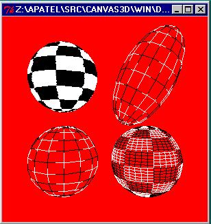
Goal : To experiment with creating spheres with different options. To change the surface options, background options, and to share surfaces on multiple shapes. Also, to control the complexity of a shape item.
Step 1 and Step 2 : Repeat as in the above example.
Step 3 : Create few surfaces. Say, let's create a red material, a surface with tiger.ppm image, a surface with lena.ppm and another with checker.ppm.
% set surf1 [ .c create surface -diffuse { 1 0 0 0 } -specular { 1 0 0 0 } -emissive { 1 0 0 0 } -ramp 1 ]
% set surf2 [ .c create surface -texture tiger.ppm -ramp 1 ]
% set surf3 [ .c create surface -texture lena.ppm -ramp 1 ]
% set surf4 [ .c create surface -texture checker.ppm -ramp 1 ]
Step 4 : Now let us create some spheres. One sphere is a default one. One has very high number of rings and sections. We put checker.ppm over them and see them in wireframe. These sphere are translated to different locations (the lower two spheres in the demos).
% set sphr1 [ .c create sphere -radius 5 -surface $surf4 ]
% set sphr2 [ .c create sphere -radius 5 -rings 40 -sections 40 -surface $surf4 ]
% .c fill $sphr1 wireframe
% .c fill $sphr2 wireframe
% .c translate $sphr1 -6 -6 0
% .c translate $sphr2 6 -6 0
Step 5 : Still more spheres. Let us keep one as it is in solid mode, while let us elongate the other and see it in wireframe mode. Also rotate and translate them (the upper two spheres in the demos).
% set sphr3 [ .c create sphere -radius 5 -surface $surf4 ]
% set sphr4 [ .c create sphere -radius 5 -rings 10 -sections 10 -surface $surf4]
% .c fill $sphr4 wireframe
% .c translate $sphr3 -6 6 0
% .c scale $sphr4 1 2 1
% .c scale $sphr4 x 1.2
% .c translate $sphr4 6 6 0
Step 6 : Let's change the background to red.
% .c itemconfigure $view -background $surf1
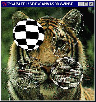
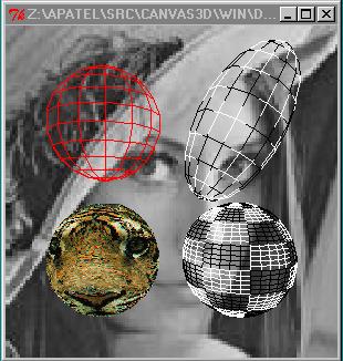
Step 7 : Let's change the background to other surfaces. Also the surfaces on the spheres.
% .c itemconfigure $view -background $surf3
% .c itemconfigure $sphr3 -background $surf1
% .c itemconfigure $sphr1 -background $surf2
Here, in this demo we show how easily we can change our mind and try out different options repeatedly on the different items in Canvas3D. This demo also shows the same item with its different options. See how the texture images are shared between multiple objects. And how the shape items are transformed into the coordinate system. A unique feature noticed in this demo is the control over the complexity of a shape that we obtain by specifying the number of rings and sections for a sphere. Also, use of material without texture images is demonstrated.
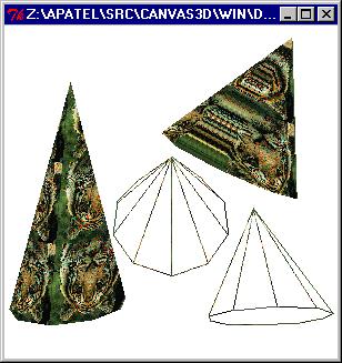
Goal : Experiments with cones.
Try running the different test files submitted with the source code. We will try to put more online demos soon, exploring more and more features of Canvas3D.
Ankit Patel (apatel@cs.cornell.edu)