CS4670/5670: Computer Vision, Fall 2015
Project 4: Single View Modeling
Brief
- Assigned: Thursday, April 9, 2015
- Code Due: Wednesday, April 22, 2015 (by 9:00am)
- Written Component Due: Wednesday, April 22, 2015 (by 9:00am) (Note both are due at the same time)
- Artifact Due: Wednesday, April 22, 2015 (by 11:59pm)
- This assignment should be done in teams of 2 students.
Introduction
In this assignment, you will fill in various routines and ultimately create 3D texture-mapped models from a single image using the single view modeling method discussed in class. The steps of the project are:
- Image acquisition
- Calculate vanishing points
- Choose reference points
- Compute 3D coordinates of several points in the scene
- Define polygons based on these points.
- Compute texture maps for the polygons and output them to files.
- Create a 3D texture-mapped VRML model
- EXTRA CREDIT: Create a reverse perspective paper cutout of the object.
- Submit results
Downloads
- Skeleton code Available through git (this should help make distributing any updates easier). With git installed, you can download the code by typing (using the command-line interface to git)
- There are certain OpenGL libraries which you will need to install on your VM for this assignment. All you have to do to obtain the needed libraries is open up the terminal within your VM and type:
>> sudo apt-get install freeglut3-dev libgl1-mesa-dev libglu1-mesa-dev libxxf86vm-dev
- Written component of this assignement is available on CMS
- Solution executable here. To run the solution make sure you place the executable in your skeleton folder or else you will get errors.
- Test images and model files are available here
For those that are already using git to work in groups, you can still share code with your partner by having multiple masters to your local repository (one being this original repository and the other some remote service like github where you host the code you are working on); here's a reference with more information.
To Do
Written Component
To ensure that you have a solid understanding of the Projective Geometry concepts used throughout this project, we've provided you with a written assignment which is to be turned in at the same time as your code. However, you should complete these problems before you start coding for it to help you. Later you should be able to apply the work you did here to assist you when coding sameXY() and sameZPlane(). These problems are available for download on CMS.
Image Acquisition
For this assignment you should take high resolution (preferably at least 800x800) images or scans of at least two different scenes. One of your images should be a sketch or painting. For instance, a photo of a Greek temple and a painting of Leonardo da Vinci's "The Last Supper" might be interesting choices. (We don't want everyone in the class to do these objects, however.) Note also that the object you digitize need not be monumental, or be a building exterior. An office interior or desk is also a possibility. At the other extreme, aerial photographs of a section of a city could also be good source material (you might have more occlusion in this case, necessitating some manual fabrication of textures for occluded surfaces). Be sure to choose images that accurately model perspective projection without radial distortions. You'll want to choose images that are complex enough to create an interesting model with at least ten textured polygons, yet not so complex that the resulting model is hard to digitize or approximate.
Calculating Vanishing Points
Choose a scene coordinate frame by defining lines in the scene that are parallel to the X, Y, and Z axis. For each axis, draw more than two lines parallel to that axis and try to make them as long as possible and far apart in the image. The intersection of these lines in the image defines the corresponding vanishing point which may be "at infinity". Use high resolution images, and use the zoom feature to specify line endpoints with sub-pixel accuracy. A small number of "good" lines is generally better than many inaccurate lines. Use the "save" feature in your program so that you don't have to recalculate vanishing points every time you load the same image.
TODO: BestFitIntersect() in svmmath.cpp
Compute the best intersection point of 3 or more lines in a least squares sense. Here is a write-up for a recommended method that extends the cross-product method discussed in class to return the best intersection point of 3 or more lines in a least squared sense. Note: Pay close attention to how each matrix datatype is indexed. Matrices from Eigen (i.e. A) use parenthetical indexing, while most others use square brackets.
Choose Reference Points
You will need to set the reference points as described in lecture. One way of doing this is to measure, in 3-D, when you shoot the picture, the positions of 4 points on the reference (ground) plane and one point off of that plane. The 4 reference plane points and their image projections define a 3x3 homography matrix H that maps X-Y positions of points on the ground plane to u-v image coordinates. The fifth point determines the reference height R off of the plane, as described in lecture. Alternatively, you can specify H and R without physical measurement by identifying a regular structure such as a cube and choosing its dimensions to be unit lengths. This latter approach is necessary for paintings and other scenes in which physical measurements are not feasible. If you'd like, you can use the X and Y vanishing points as two of the reference points on the plane. In this case, you need to specify only 2 more on the plane and one off the plane.
Once you have specified reference points and push them onto stack, you can run "Tools->Compute Homography" which will compute and store a homography for later use.
TODO: ComputeHomography() in svmmath.cpp
Compute the homography H from the plane specified by points to the image plane, as well as Hinv, the inverse of H. This is used to compute the homography for the reference plane, as well as the polygonal patches you create. In case of an arbitrary polygonal patch in 3D space, you need to convert the coordinate system first. See this document for a more detailed explanation.
TODO: ConvertToPlaneCoordinate() in svmmath.cpp
Convert the coordinate of points on the designated plane to the plane coordinate system, as described in above mentioned document. This is called from ComputeHomography to compute homographies from polygonal patches you defined in the scene. Save the final scales you apply to the u and v dimensions to the output parameters uScale and vScale.
Compute 3D Positions
You will compute 3D positions of any new points using your information from the reference points, vanishing points, and homography. When completing these TODOs, keep in mind the work you did on the written portion of this assignment. You might find that you can use similar methods to compelte your solution. In general, to compute the 3D positions, you can combine two different techniques: point: in-plane measurements and out-of-plane measurements which are:
TODO: sameXY() in ImgView.inl
Compute the 3D position of a new point that is directly above another point whose 3D position is already known. See the slides for measuring height (Projective Geometry).
TODO: sameZPlane() in ImgView.inl
Compute the 3D position of a new point that is on the same plane as another point whose 3D position is already known. A special case of this is a point on the reference plane. In this case, the reference homography H can be used to compute its 3D position. More generally, see the man on the box slide from lecture (Projective Geometry slide 16), where the given reference point is t1, the new point is m0, and you want to compute the point b0 (once you have b0, you can compute its X and Y positions using H-1). Note that the man is not used here, we're only interested in a point on the box. You may use vz instead of t0 to help find b0. While you're not given the image position of b1, you can compute it from its 3D coordinates (knowing it has the same X-Y coords as t1 and is on the ground), using H.
Besides these two techniques, you will be implementing a set of functions which compute 2D/3D positions of the corners of a box given some existing reference corners:
TODO: solveForOppositeCorners() in ImgViewBox.cpp
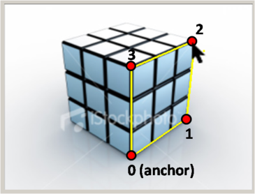
Given the 2D position of corners 0 and 2 on an XZ rectangle, compute the 2D positions of the other two corners (with indices 1 and 3). You'll need to use the vanishing points and construct various lines to find the points. The indexing of the corners is shown here:
TODO: solveForOppositeFace() in ImgViewBox.cpp
Given the 2D positions of corners 0,1,2, and 3 on a
box and the current mouse position, compute the
2D positions of the other four corners (with indices
4, 5, 6, and 7). Again, you'll need to use the vanishing points and
construct various lines to find the points. The indexing of the
corners is shown here:

TODO: find3DPositionsBox() in ImgViewBox.cpp
Given the 2D position of all eight corners of a box (indexed according to the previous image), and the 3D position of the anchor (point 0), compute the 3D coordinates of all points. You will want to first implement the sameXY and sameZPlane routines.
Compute Camera Position
You can solve for the height of the camera using the horizon as discussed in class (Projective Geometry slide 8). You may find the SameXY routine useful here.
To solve for the X and Y world coordinates of the camera, first imagine a point C0 on the ground plane that lies directly below the camera (this point has the same X and Y coordinates as the camera), as shown in the figure below.

If we can find where C0 projects into the image, sameZplane will tell us its XY coordinates and we'll be done. So where does C0 project? The projection is the intersection of the ray from C0 through the camera center with the image plane. Notice that this ray is vertical---it goes straight up towards the Z point at infinity, [0 0 1 0]T). Notice also that every point on this ray (including [0 0 1 0]T) projects to the same point in the image. Hence, the projection of C0 is the same as the Z vanishing point, vz (pretty neat, huh?). vz in combination with sameZplane gives you the X and Y coordinates of the camera.
TODO: computeCameraParameters() in camera.cpp
Compute the position of the camera, assuming the reference homography and reference height have already been specified.
Compute Texture Maps
Use the points you have measured to define several planar patches (polygons) in the scene. Note that even though your measurements may be in horizontal or vertical directions, you can include planes that are slanted, such as a roof.
The last step is to compute texture map images for each of these polygons. Your program will store a separate texture image for each polygon in the scene, created by applying a homography to the original photo. You need to solve for the appropriate homography for each polygon. If the polygon is a rectangle in the scene, e.g., a wall or door, all that is needed is to warp the quadrilateral image region into a rectangular texture image. More generally, you will need to convert the coordinate system of the polygon to align with the texture image. See this document for a more detailed explanation.
Create a VRML model
For each image you work from, create a VRML model with at least 10 texture-mapped polygonal faces. The skeleton code will create the VRML file for you but you need to add texture map images and masks for each polygon, in .gif format. This file will be used to view the model you created in a VRML viewer like the one we have suggested below.
EXTRA CREDIT: Create Reverse Perspective
Go here to get a detailed conceptual explanation on this extra credit item.
What to turn in
Please turn in a file code.zip to CMS. Along with your code you will be expected to turn in written_soln.pdf containing your answers for the written portion of this assignment. For your artifact, you will be turning in 4 files via CMS to the Project 4 Artifact turnin:
- An image named artifact.jpg that will be used for voting. This should be a screenshot of the artifact VRML file you wish to turn in, from a nice angle (This is possible inside the VRML viewer we suggested, simply using the GUI). It should be a full-resolution copy, we will produce thumbnails as needed. Note that you should select as your artifact model the VRML file you want to use for voting.
- An image named input.jpg that will be also be used for voting. This is the original input image you used to create your artifact model. It should also be a full-resolution image.
- A zip file named model.zip that contains a file model.wrl corresponding to the VRML model you wish to use for voting. The zip file should also contain any texture maps needed to view your model. This file should expand into the current directory (i.e., should be a flat zip file)
- A zip file named webpage.zip that shows off the 2
VRML files you create, including (note that there will be
some overlap with model.zip above):
- source images, show them both in their original form and with annotations and marks to show which points and lines you digitized (e.g., from a screen shot of the user interface). Give details on where you got the image (name of building, book and page number, artist, etc)
- a still image of a new view of the reconstructed VRML model, fairly far away from the input image.
- some of your texture maps, show some of the more interesting ones, commenting on any hand retouching you did to fill in occluded textures in the background (perhaps show before and after retouching, if it was significant)
- Include at least one non-quadrilateral object to make the scene more interesting.
- VRML files for each input image.
Resources
- Class lecture notes on projective geometry and single view modeling
- Single view modeling web pages and paper by Antonio Criminisi and colleagues.
- There are also some projective geometry tutorials online.
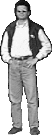
- VRML: The Virtual Reality Modeling Language, a file format for interactive 3-D models (a.k.a. virtual worlds) on the Internet. view3dscene is a VRML viewer that works well in the VM and is easy to set up. The VM is 32-bit Linux. We have put a sample VRML file (it is a text file) online. You should see a guy with sunglasses standing on a plank. The guy should look like a cardboard cutout (not a rectangle) if transparency is working. The two texture gif files, floor.gif and io.gif, are in the same directory. More on the VRML file format. Note that we'll only be using a fraction of VRML's capabilities.
- NOTE: Images used in this VRML viewer are required to have the
.gifextension. You can find.tgato.gifconverters online. An alternative is to install ImageMagick withsudo apt-get install imagemagick. You can then runconvert image.tga image.gifto do the image conversion. - For image editing we recommend using a program like gimp, but whatever you use be sure to choose an image editor that supports transparent gifs.
Additional Extra Credit
Here is a list of suggestions for extending the program for extra credit. You are encouraged to come up with your own extensions. We're always interested in seeing new, unanticipated ways to use this program!
![]() Show the camera position in
each VRML file, marked by a sphere or other shape.
Show the camera position in
each VRML file, marked by a sphere or other shape.
![]() Merging models from multiple images. For instance, create a complete model of a
building exterior from a few photographs that capture all four sides.
Merging models from multiple images. For instance, create a complete model of a
building exterior from a few photographs that capture all four sides.
![]() Implement a method for automatically computing the three vanishing points.
Implement a method for automatically computing the three vanishing points.
![]()
![]() Extend the method to create a 3D model from a cylindrical panorama.
Hint: parallel lines in a panorama sweep out a curved path--you need to
determine what this curve is.
Extend the method to create a 3D model from a cylindrical panorama.
Hint: parallel lines in a panorama sweep out a curved path--you need to
determine what this curve is.
Monster bell: Warning: this bell is extremely difficult!
![[monsterbell]](monsterbell.gif)
Automatically compute the geometry of a 3D box approximating the shape of the room in an image, as in this paper.
Acknowledgments
The instructors are extremely thankful to Prof. Steve Seitz for allowing us to use this project which was developed in his Computer Vision class.
Last modified on April 9, 2015