CS4621 PPA2 Shaders and Textures
Out: Wednesday October 21, 2015
Due: Monday November 2nd, 2015 at 11:59pm
Work in groups of 2


Deformable flower shader, fire shader and wood shader
Overview
In this assignment, you will implement several shaders in GLSL and integrate them into the Scene environment from the cs4620 scene and shaders assignments. You will also map objects with texture coordinates, and use textures in your shaders. We have provided you with a set of scenes to tests your implementations that can be found under data/scenes/ppa2/
There are three main components to the assignment that implement a suite of visual effects using shaders:
- Use the vertex shader to implement a non-linear transformation making a flower bend to follow a light source
- Implement a shader that use textures to simulate a finished-wood appearance model
- Model a simple fire effect with a shader that uses Perlin noise to generate the fire color and displacement patterns
For the shader tasks, you will use the scene interface from cs4620 a3 that allows the user to select what shader to apply to each object in the scene. For Task 1, you can use your manipulators or scene toolbar to move around the light that should interact with the flower shader
We have marked all the functions or parts of the functions you need to complete for the assignment with TODO#PPA2 in the source code. To see all these TODO annotations in Eclipse, select the Search menu, then File Search and type TODO#PPA2 (They can also be viewed through the Task List). You only need to modify the sections marked with TODO#PPA2 unless of course you want to add some additional cool shader or user interface functionality for extra credit. All other parts have been implemented for you.
Task 1: Flower Shader
Files: Flower.vert, Flower.frag

The flower mesh bending nonlinearly to follow a light. The unbent mesh is second from the left
In this part, you will implement a shader that transforms a flower mesh to make the flower bend towards the light source in the scene. In your shader program, the vertex shader will transform the mesh vertices and normals, and the fragment shader will render the bent flower using per-pixel Phong shading. To test the shader, we provide a scene data/scenes/flower.xml that loads the flower model and a light source, which we can manipulate to observe how the position of the light affects the shape of the flower.
The Transformation
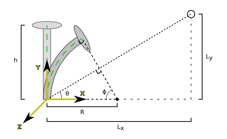
Geometry of the flower-bending method
The figure above shows the flower mesh before and after it is bent to point at the light. For now, assume that the light source lies in the $x-y$ plane. Before applying the transformation, the flower mesh is located at the origin and extends to a height $h$ along the $y$ axis. The bending transformation takes the line running up the center of the flower stalk (the green line in above figure) and maps it to an arc of a circle, such that:
- The base of the bent stalk remains at the origin.
- The length of the bent stalk equals the length $h$ of the stalk in the un-modified mesh.
- The top of the bent stalk points in a direction parallel to the vector from the origin to the light source.

Transforming points on the flower
This fully defines how to transform the center of the flower stalk. Finally, we can use $\phi$ and $R$ to define how to move an arbitrary point $\mathbf{p}$ on the mesh to its transformed position $\mathbf{p}'$. First of all, since all of the bending happens along the $x-y$ plane, the $z$ coordinates of vertices in the mesh are unchanged by the transformation. To get $\mathbf{p}'_x$ and $\mathbf{p}'_y$, notice that vertical lines in the untransformed flower are mapped to arcs of circles centered at point $(R, 0, z)$ with different radii. In this mapping, $\mathbf{p}_x$ determines the radius of the circle containing $\mathbf{p'}$: for example, if $\mathbf{p}_x = 0$, the circle containing $\mathbf{p}'$ has radius $R$. Then, the height $\mathbf{p}_y$ of the original point determines where $\mathbf{p}'$ lies on this circle: for example, if $\mathbf{p}_y = 0$, then $\mathbf{p}'$ is at angle $0$ above the x axis, and if $\mathbf{p}_y=h$, then $\mathbf{p'}$ is at angle $\phi$ above the $x$ axis.
Similarly, the normal $\mathbf{n}$ at $\mathbf{p}$ must be transformed to produce a corresponding normal $\mathbf{n'}$ for the bent flower. To determine this transformation, notice that the small region around $\mathbf{p}'$ in the bent flower is rotated compared to the corresponding region around $\mathbf{p}$; this rotation is what must be applied to the original normal $\mathbf{n}$.
Note: When the flower is not bent (the light is directly above it), $R$ in the equations above becomes infinite. You should account for this special case within the shader.
The Coordinate Frame

Defining a convenient frame for the flower problem. The axes of the object's local frame are in black, and the light-aligned frame is in yellow.
In the section above, we simplified our math by assuming the flower and the light source both lie in the $x-y$ plane. In general, the light source might not be on the $x-y$ plane in the coordinate frame of the flower (the black axes). To fix this, define a new coordinate frame (the yellow axes) in which the flower center and the light source do fall on the $x-y$ plane.
The matrices objToFrame and frameToObj, which map from the object's frame to the yellow light-source-aligned frame and vice versa, are already calculated for you.
Putting It All Together
Before starting to code the shader, we recommend using the figures above to come up with explicit formulas for $\mathbf{p}'_x$ and $\mathbf{p}'_y$ based on $\mathbf{p}_x, \mathbf{p}_y$, and the values marked in the geometry figure.
In total, the work done by your shaders will look like this:
- Map the flower (vertices and normals) into the frame aligned with the light source.
- Apply the transformation shown in the flower geometry figure.
- Map the transformed geometry back to object space, and then to world space.
- Perform per-pixel Phong shading using the world space, transformed geometry.
Task 2: Finished-wood Shader
Files: Wood.vert, Wood.frag
Polished wood has a beautiful and distinctive appearance that is mostly caused by directional reflectance from the subsurface fibers of the material. The scattering from the wood fibers below the surface, resulting in a highlight that occurs on a cone with an out-of-plane axis (see Fig 1 and Fig 2 below). A simple anisotropic model was proposed by Marschner et. al. [Siggraph 05] that makes use of a four parameter equation to model this effect with a fuzzy gaussian cone around the fiber direction. \begin{align*} L_d &= k_d I \max (\mathbf{n} \cdot \mathbf{l}, 0) &\text{(diffuse)}\\ L_s &= k_s I \max (\mathbf{n} \cdot \mathbf{h}, 0)^n &\text{(specular)} \\ L_f &= k_f I \frac{g(\beta,\psi_h)}{cos^2(\frac{\psi_d}{2})} &\text{(subsurface)} \\ \psi_d &= \psi_r - \psi_i\\ \psi_h &= \psi_r + \psi_i\\ \psi_r &= sin^{-1}(\frac{v \cdot u}{n_{cellulose}})\\ \psi_i &= sin^{-1}(\frac{l \cdot u}{n_{cellulose}})\\ \\ L &= \begin{cases} L_d + L_s + L_f & \text{if $\mathbf{n} \cdot \mathbf{l} > 0$} \\ 0 & \text{otherwise} \end{cases} &\text{(final material color output)} \end{align*} where $\mathbf{u}, \mathbf{\beta}, \mathbf{n}, \mathbf{h}, \mathbf{v}, \mathbf{l}$ are the fiber direction, highlight cone width, surface normal, half-vector, viewing and light directions respectively and $n_{cellulose}$ = 1.55. $\mathbf{g( )}$ is a 1D gaussian of the form $\frac{1}{\beta\sqrt{2\pi}}e^{-\frac{\psi_h^2}{2\beta^2}}$
The final equation for $L$ has two cases because if $\mathbf{n} \cdot \mathbf{l} < 0$, the light source is behind the surface, so neither the diffuse nor the specular term should contribute to the resulting color.

Figure 1: Light reflecting from a matrix of subsurface fibers. The reflection from the fibers has equal incident and reflected angles, but because the fibers are tilted the angles are different at the surface

Figure 2: The basic shape of the subsurface reflection from fibers inclined downward, parallel to the surface, and inclined upward
There are four parameters that are needed for the anisotropic part of the wood model which we store in separate texture maps as shown in Figure 3. We can use multitexturing in our shaders to load all of these texture maps and use them to look up a value based on our uv mapping coordinates. Look at the comments inside the shader files for more information.
Your job is to use the provided texture samplers to access and convert the texture pixel data to a suitable form (note that some conversion between $[0,1]$ and [-1,1] will be required) and write the shader code that implements the finished wood model according to the above equations. We have provided you with several test scenes under data/scenes/ppa2/ to help you test and showcase the implementation.


Figure 3: The different parameter texture maps for the wood model: fiber axis($u$), highlight width ($\beta$), diffuse component ($k_d$) and fiber color ($k_f$)
Task 3: Animated Fire Shader
Files: Fire.vert, Fire.frag
In this shader, you are going to use Perlin Noise to generate a simple fire effect. We give you two textures, noise.png and fire.png. This shader samples from the noise texture to determine what we are going to sample from the fire texture.
There are many ways in which you can create such a texture. We describe one way that produces good results that you are required to implement. After implementing this variant, you can play around with alternative augmented versions of this basic approach.
To sample from the noise texture, we can calculate three sets of texture coordinates. The variables that you use for this are the uniform variable time, and the constants texture_scales and scroll_speeds. To create each set of texture coordinates, we will first scale our input $UV$ coordinate by each of the scales specified in texture_scales. We then want to scroll each of our $V$ texture coordinates based time. The speed at which this coordinate scrolls for each of our three samples is specified in the scroll_speeds variable, which has units of $V$-coordinates per second. The time uniform specifies how much time has passed since the program began in seconds. Please note that texture2D (called by the get*Color() methods) will clamp the texture coordinate values between $0.0$ and $1.0$, however, we want it so that the texture wraps around infinitely. This means when you reach $1.0$ you start back at $0.0$. From here, average all of the texture values and use this to sample from the fire texture.
You can also achieve a more interesting fire effect by modulating the vertex position in a similar as the displacement mapping in the cs4620 shaders assignment. It is up to you to experiment with the parameters to animate positions and color in a clever way until you achieve an interesting fire effect beyond our outlined baseline implementation described above. Feel free to modify default variable values, add extra variables, etc.

An example of an augmented fire shader
What to Submit
Submit a zip file containing your solution organized the same way as the code on Github. All the code you have written should be well commented and easy to read. The header comments for all modified files should indicate the appropriate authorship. Include a readme in your zip that contains:
- You and your partner's names and NetIDs.
- Feedback on the assignment.
- Explanation of any implementation choices you made.
- Any problems with your solution.
- Anything else you want us to know.