CS 4621 PPA1 WebGL Ray
Out: Friday February 17, 2017
Due: Friday March 3, 2017 at 11:59pm
Work in groups of up to 4
Overview
In this programming assignment, you will implement a simplified GPU version of the CS4620 raytracer (Ray 1). The goal here is not to reproduce all the features we have seen in the other assignment but rather to give you some practice on WebGL programming.
WARNING: WE THINK THIS ASSIGNMENT IS LONG. START EARLY.
What You Code Should Be Able to Do
Logistics
First, clone the CS 4620 web repository.
You will find the template code for this assignment in the cs4621/ppa1_student directory.
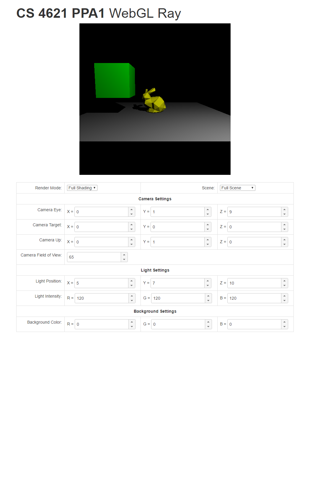
Inside the directory, open index.html, and you should see something like this.
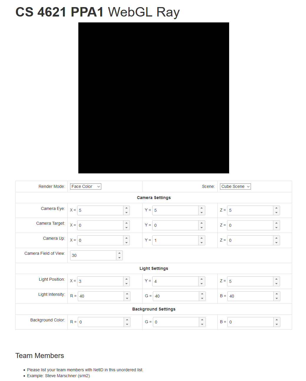
Please modify index.html so that it performs ray tracing and shows the output in the black canvas
on the top of the web page. You may also add other code to the directory. However, do not use any 3D rendering
framework such as three.js. Linear algebra libraries such as
glMatrix are fine. Our solution code, however, does not use any
extra code besides what is already in the ZIP file.
Once you're done writing your solution, ZIP the cs4621/ppa1_student, and submit
the ZIP file to CMS.
Implementation Details
Camera and Ray Generation
Instead of a more involved camera model in the Ray 1 assignment, the camera model in this assigment is a little simpler. It is specified by 4 parameters:
- Eye = the camera's position in world space.
- Target = the point in world space that the camera is looking at.
- Up = the camera's up vector.
- Field of view (FOV) = an indication of the extent of the scene observed by the camera. It is an angle, measured in degrees. You can find out more about FOV in this Wikipedia article. Since our canvas is a square, the horizontal FOV is equal to the vertical FOV. So, there's one FOV instead of two.
To generate rays from the camera, first form an orthonormal basis $[\mathbf{x}, \mathbf{y}, \mathbf{z}]$ as follows: \begin{align*} \mathbf{z} &= \mathrm{normalize}(eye - target) \\ \mathbf{x} &= \mathrm{normalize}(up \times \mathbf{z}) \\ \mathbf{y} &= \mathrm{normalize}(\mathbf{z} \times \mathbf{x}) \end{align*}
The image plane is parameterized by $(x,y)$ coordinates where both $x$ and $y$ ranges from $[-1,1]$. So, consider drawing a full screen quad so that the bottom-left corner corresponds to $(-1,-1)$ and the top-right corner corresponds to $(1,1)$.
All rays originate from the camera's eye position. The ray associated with image plane coordinate $(x,y)$
has direction:
$$\mathbf{d} = \mathrm{normalize}(-\mathbf{z} + (s\ x)\ \mathbf{x} + (s\ y)\ \mathbf{y})$$
where
$$ s = \tan \bigg( \frac{\pi}{180} \frac{FOV}{2} \bigg).$$
In other words, we convert $FOV/2$ to radian and compute its tangent.
Note that the ray starts right off from the eye position, not from a plane that is in front of it.
This is because our camera model does not have something equivalent to projDistance
like the one in the Ray 1 assignment.
The camera can be controlled by the GUI elements in index.html. Its Javascript code
contains the convenience methods for retrieving the camera parameters:
getCameraEye()getCameraTarget()getCameraUp()getCameraFov()
Call these functions every frame, and pass their return values to your shader.
Light Source
All scenes we will render in this assignment has one point light source, and it is defined by two parameters: its position and intensity. These parameters can be controlled by GUI elements, and the template code's provide the following functions for retrieving their values:
getLightPosition()getLightIntesity()
Again, call these functions every frame, and pass their return values to your shader.
Background Color
If the eye ray does not hit any geometry, your shader should set the pixel to
the background color that is specified by the GUI in index.html.
Use the function getBackgroundColor() to retrieve its value.
Scenes
In the template code, we have included three scenes that you can render: the "triangle," the "cube," and
the "full" scene. You can switch between theme through the GUI. In Javascript, use the
getScene() function to retrieve the current scene specified by the GUI.
The value returned by the getScene() function is a Javascript object with the following fields:
numTrianglesis the number of triangles in the scene.-
vertexPositionsis an array containing $3 \times 3 \times numTriangles$ floating point numbers. It contains the 3D positions of the three vertices of the triangles. -
triangleColorsis an array containing $3 \times numTriangles$ floating point numbers It contains the diffuse color $(k_D)$ of the triangles.
In other words, the triangles are specified using the "separate triangles" representation.
(See CS 4620 Lecture 2.)
We would have loved to represent them using the "indexed triangle set" representation,
but WebGL did not allow us to. (Trust us. We tried.) If you would like to know how the scene objects
are created, read scenes.js.
In your shader, you should create a uniform array that can store all the vertex positions and triangle colors. For example,
uniform vec3 vertexPositions[MAX_TRIANGLES*3];
uniform vec3 triangleColors[MAX_TRIANGLES];
MAX_TRIANGLES
to $132$. Update these uniforms with the data in the scene object every frame.
With these uniforms, the 3 vertices of the $i$th triangle are given by:
vertexPositions[3*i], vertexPositions[3*i+1], and vertexPositions[3*i+2].
The color of the $i$th triangle is given by triangleColors[i].
Render Modes
Your ray tracer should support the following rendering modes
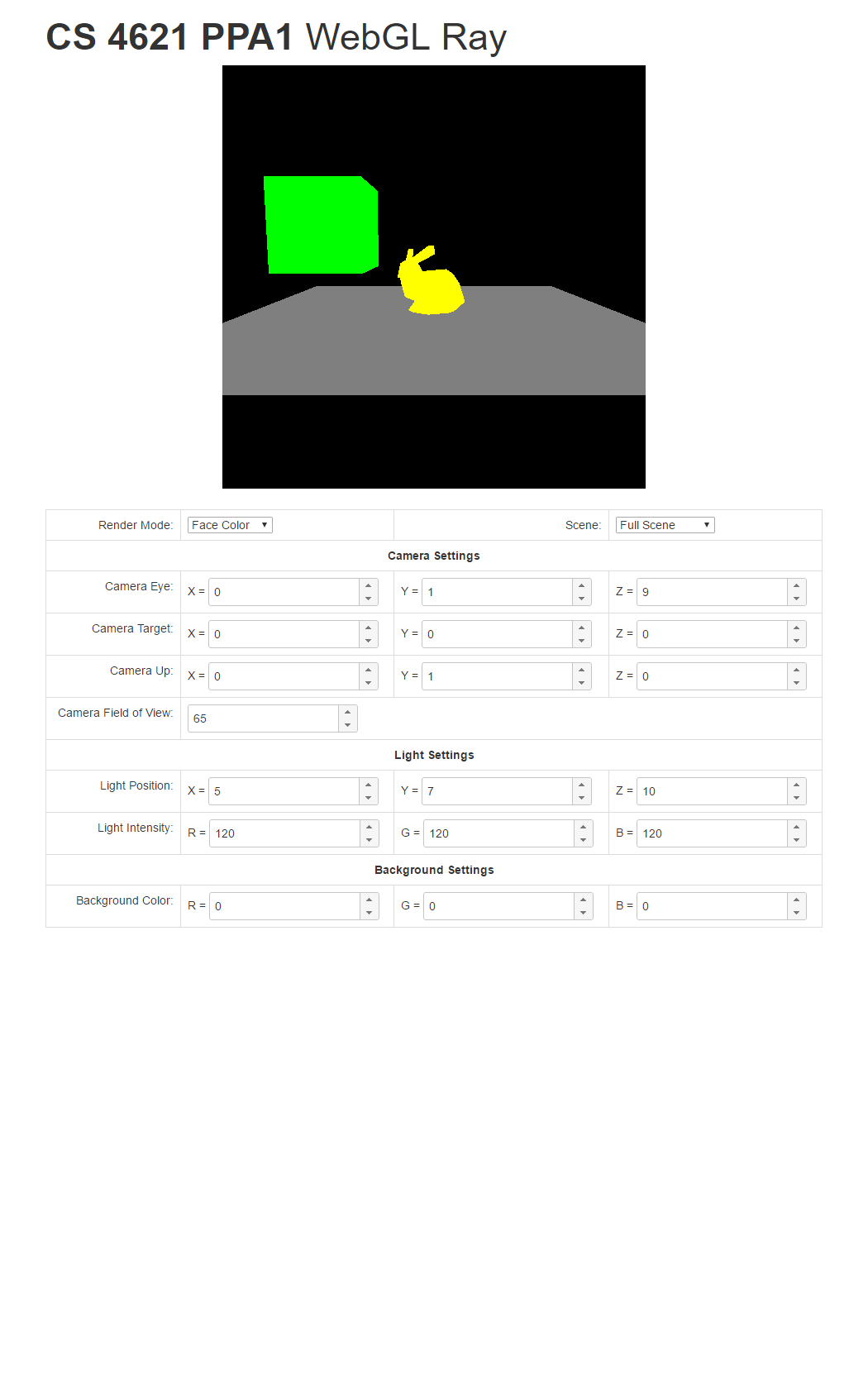
- Face color mode: If the ray associated with a pixel hits a triangle, set that pixel to the triangle's color.
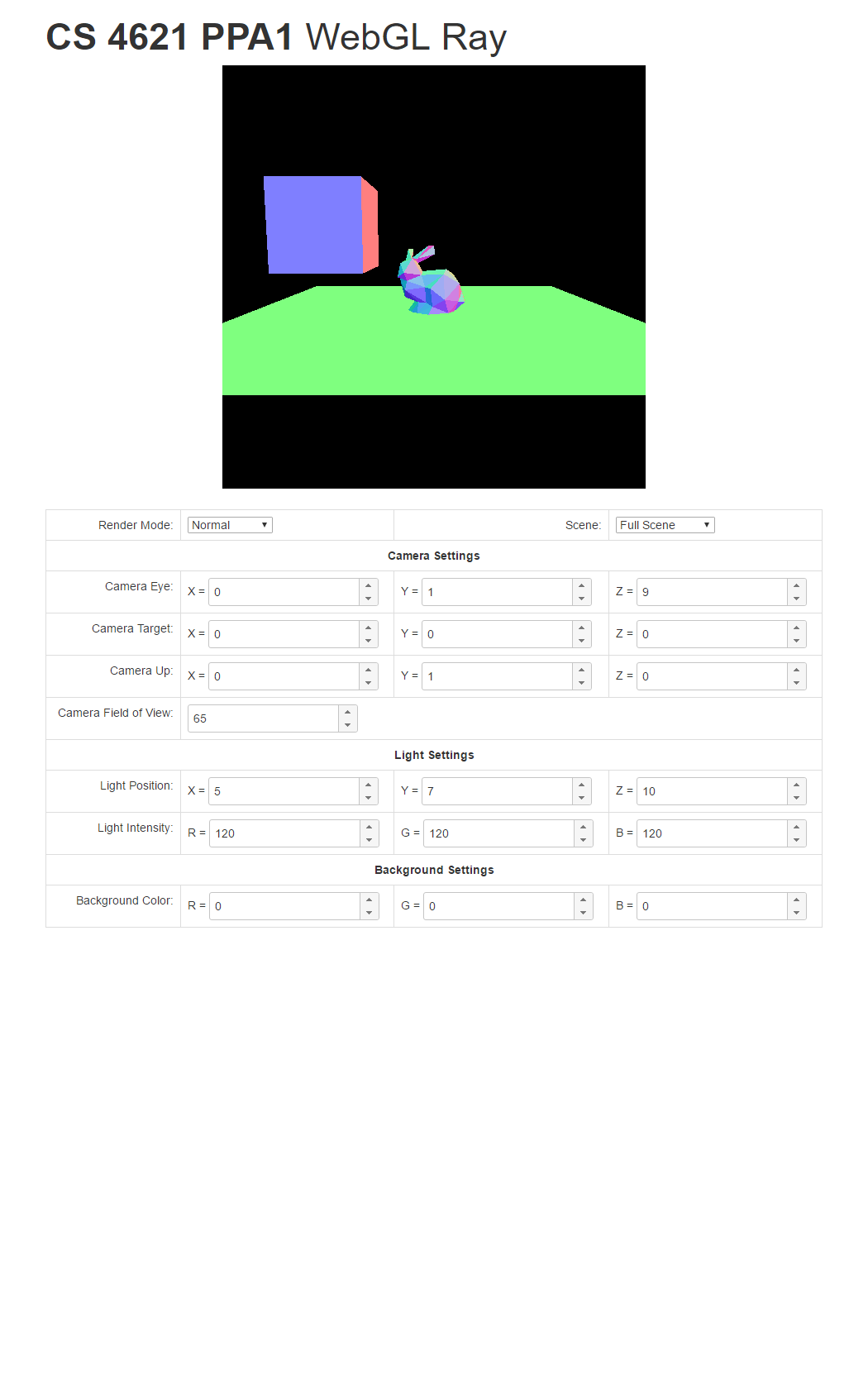
- Normal mode: If the ray associated with a pixel hits a triangle, compute the triangle's normal vector $\mathbf{n}$. Then, set the pixel value to $(\mathbf{n} + (1,1,1)) / 2$
- Shadow mode: If the ray associated with a pixel hits a triangle, trace the shadow ray from the hit point to the light source. If the light is occluded, set the pixel to black. If not, set the pixel to white. DO NOT FORGET TO ADD EPSILON TO THE RAY STARTING POINT.
-
Full mode: This mode performs the full shading of a diffuse BRDF against a point light
source. If the ray associated with a pixel hits a triangle, set the pixel color to:
$$ (visibility) \times (triangle\ color) \times \max(0, \mathbf{n} \cdot \mathbf{l}) \times
\frac{light\ intensity}{r^2}$$
where
- visibility is $0$ if the light is occluded and $1$ otherwise,
- $\mathbf{l}$ is the unit vector pointing in the direction from the hit point to the light source's position.
- $r$ is the distance between the hit point and the light source.
The render mode can be changed by the GUI. You can retrieve the current rendering mode
in Javascript by calling the getRenderMode() function. It returns an integer
where $1$ means the face color mode, $2$ means the normal mode, $3$ means the shadow mode,
and $4$ means the full mode. Pass this value to your shader every frame.
Some Annoying WebGL Limitations We Would Like You to Know Before Hand
WebGL specification was written for hardward with limited capabilities. So there are something that you would be able to do in normal programming languages but cannot do in GLSL.
-
If you write a for loop, the number of iterations must be known at compile time.
This means that you cannot do something like this:
uniform int numTriangles;

for(int i=0; i<numTriangles; i++) {
    :
    :
}
But you can do something like this:#define MAX_TRIANGLES 132 for(int i=0; i<MAX_TRIANGLES; i++) { if (i >= numTriangles) break; : : } -
Array access in the fragment shader is limited. You can only index an array with an expression
made up of loop counters and constants. In other words, the following is okay:
vec3 p = vertexPosition[0];

for(int i=0; i<MAX_TRIANGLES; i++) {
    vec3 a = vertexPositions[3*i];
    vec3 b = vertexPositions[3*i+1];
    vec3 c = vertexPositions[3*i+2];
    :
    :
}
But, this is not:uniform int vertexIndex; vec3 p = vertexPositions[p];
This is why we could not use the "indexed triangle set" mesh representation with WebGL. Moreover, you could not save the index of the triangle the ray first intersect and use it to retrieve the triangle's normal or color later. There is a work around for this, but we leave it to you to figure it out.
A WebGL Feature We Would Like You to Know Before Hand
When writing a function, you can use the keywords to quantify function parameters so that
you can pass value back from the function as well. This is very useful when writing a function that
has more than one return values. The keywords you want to use
are out and/or inout. Using them, you can do this:
void computeSomething(float x, out float y, inout float z) {
    y = x + 1.0;
    z = 2.0*(x+z);
}

void main() {
    float a;
    float b = 2.0;
    computeSomething(5, a, b);
      :
      :
      :
}
After computeSomething is called, a becomes 6, and b becomes 14.
Programming Tips
Okay. So, we give you some skeleton code, and it has nothing that deals with WebGL at all. You are supposed to write all this by yourselves. There are many features to implement and many things to keep track of. How would you actually do it all?
We advice you to:
KEEP CALM AND INCREMENTALLY ADD FEATURES.Do not do it all at one time. Break the assignment to easy-to-finish and easy-to-test pieces. Here is a possible road map.
- Initialize WebGL.
- Get a WebGL context. See Exhibit #0 of Lecture 1.
- Set up your rendering loop. See Exhibit #5 of Lecture 1
-
Write a shader that draws the full screen quad and make sure it works.
- The easiest way to do this is to make use of the code in Exhibit #6 of Lecture 2.
- What is the texture coordinates of the 4 corners of the full screen quad in Exhibit #6? Are they the most convenient for this assignment?
-
Have your shader output the background color.
- Learn how to create and use uniforms from Exhibit #2 of Lecture 2
- Have your shader generate the rays. Output ray direction as color. You should see the picture changes as you change the FOV.
-
Work on the face color mode; i.e. eye ray intersection.
- Learn how to create and use uniform arrays from Exhibit #3 of Lecture 2
- Write your code to intersect just the first triangle in the mesh first.
- Get your code to work with the "triangle" scene, which has only one triangle.
- Then, write a for loop that goes through all the triangles to find the first intersection.
- Then, try to get the "cube" scene to work.
- Once you're confident, run your code on the "full" scene.
- From our experience, this step is the hardest because ray tracing is complicated in itself. It's also very easy to trip up over little details. Be patient here.
- Work on the normal mode.
- Work on the shadow mode; i.e. shadow ray casting.
- Work on the full mode.
We would like to also remind you that the exhibits are for you to use. However, do not just copy and paste them in your code. Read and understand them so that so you can modify them to do your bidding. Also, make use of the code you wrote for the Ray 1 assignment. If you have to get that part of Ray 1 fixed first, come to us for help.
To help you check your progress, we provide screenshots of the reference program's renderings of the three scenes under all the modes below.
| Triangle Scene | Cube Scene | Full Scene | |
| Face Color Mode |  |
 |
 |
| Normal Mode |  |
 |
 |
| Shadow Mode | 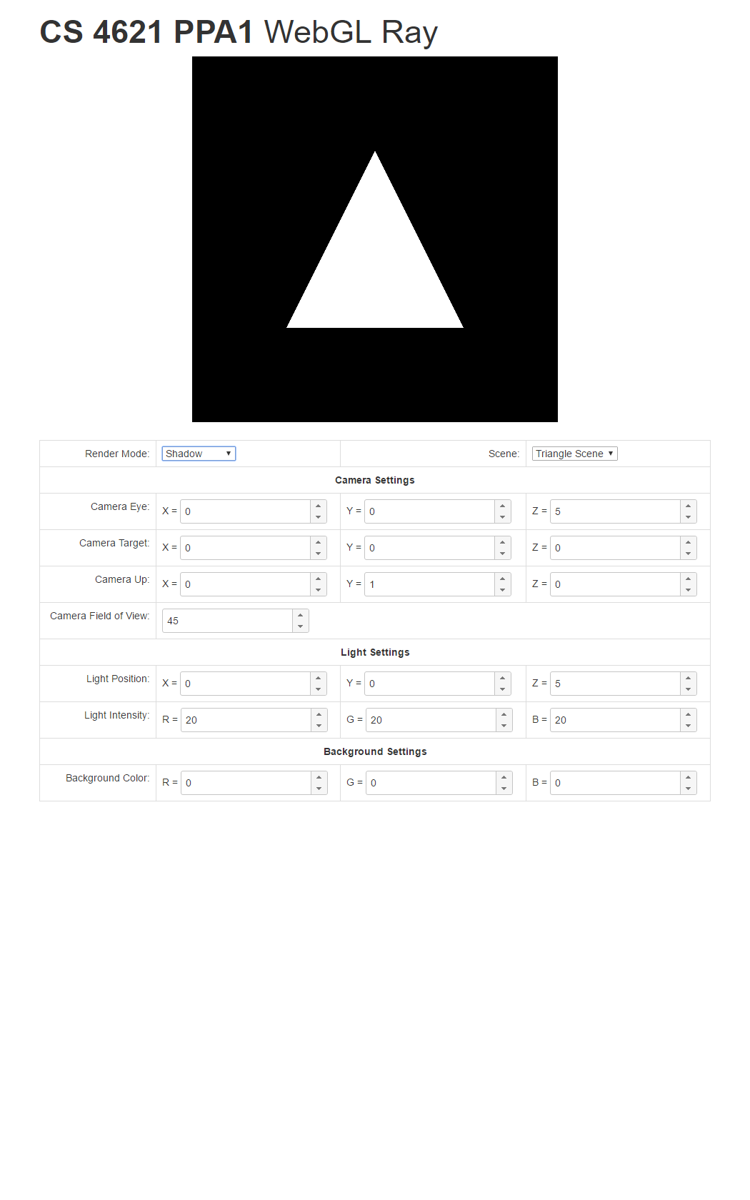 |
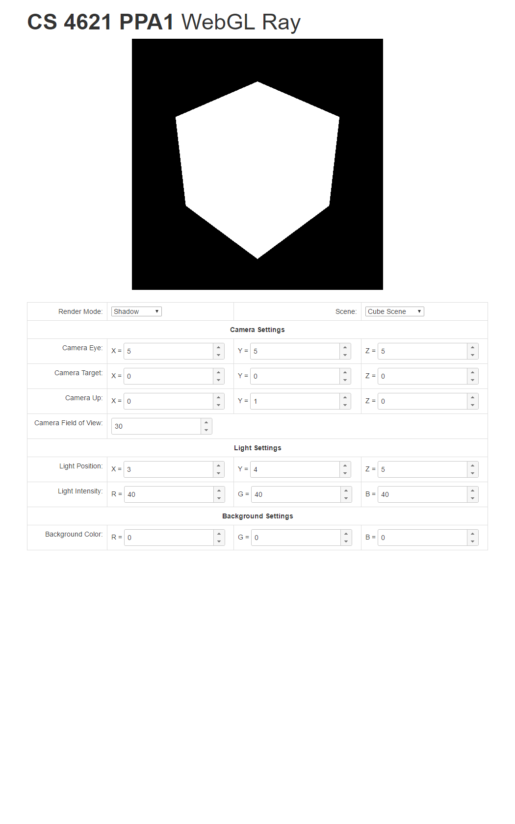 |
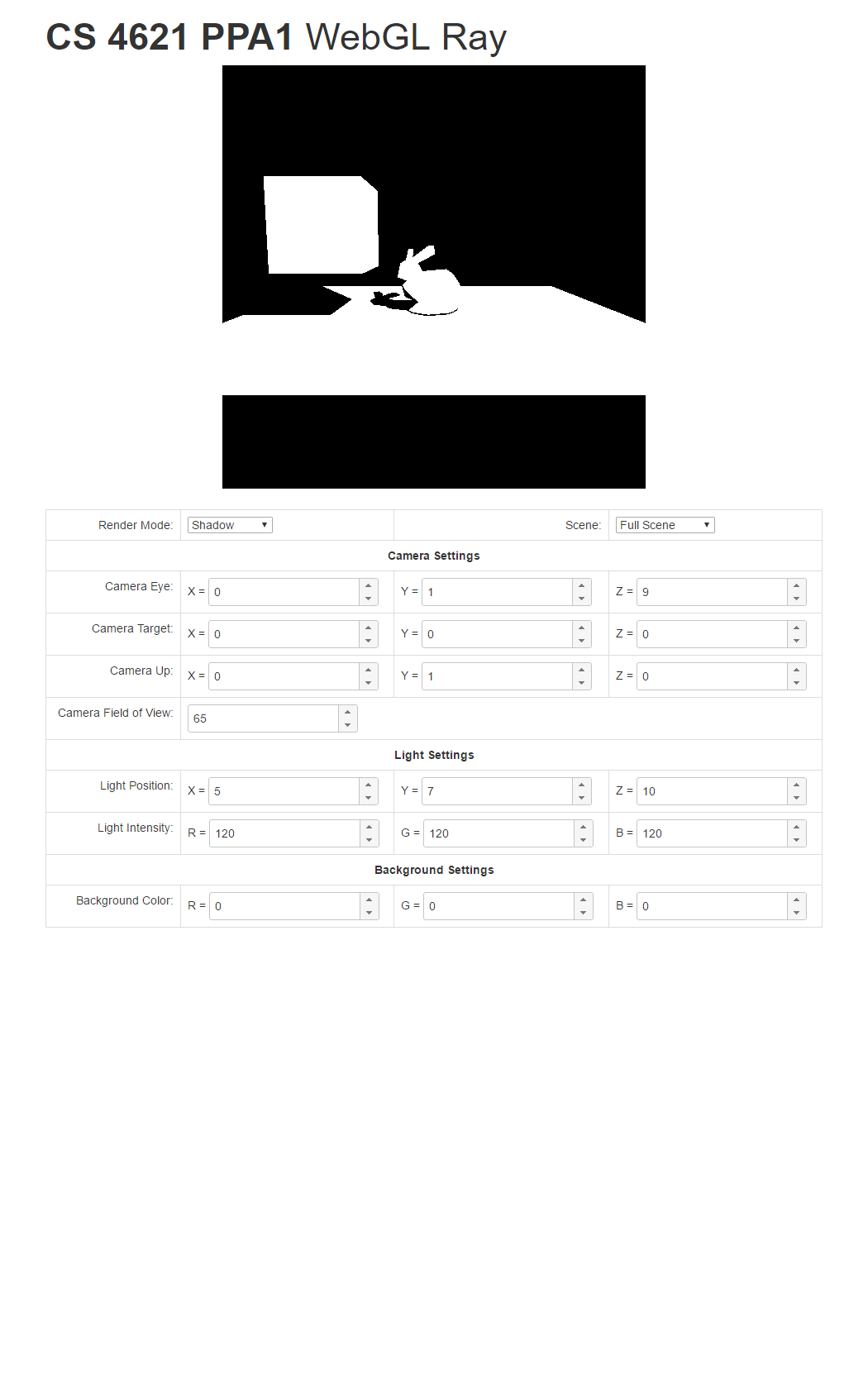 |
| Full Mode | 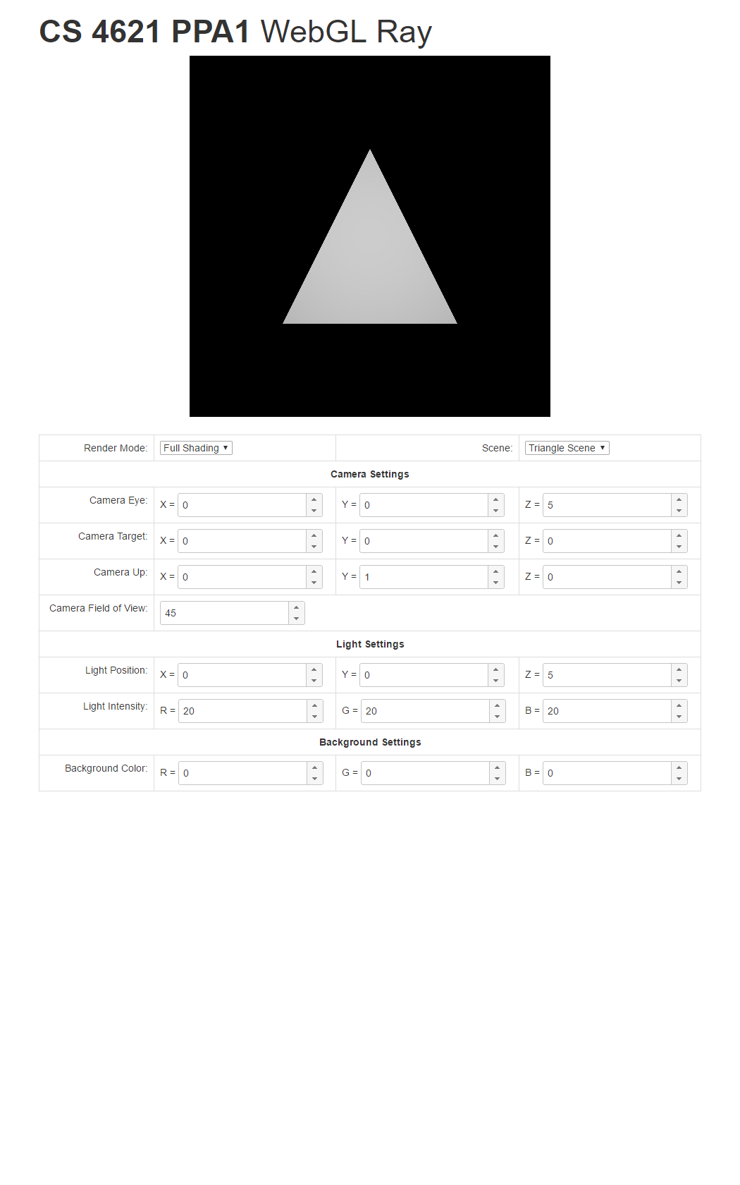 |
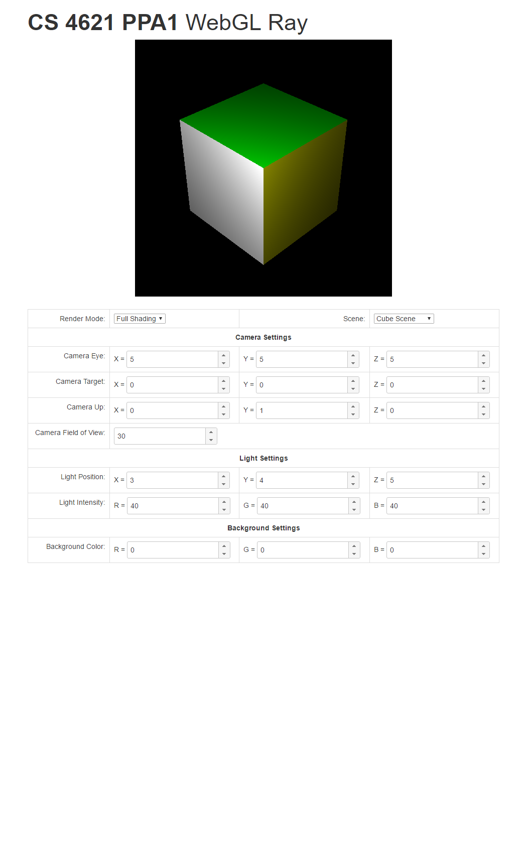 |
 |
Remember, though, to make up new test cases on your own because we will do so to test your program too. Change the background color. Move the camera and the light around. What happens when the light is inside the bunny or the box? Does your program's behavior make sense?