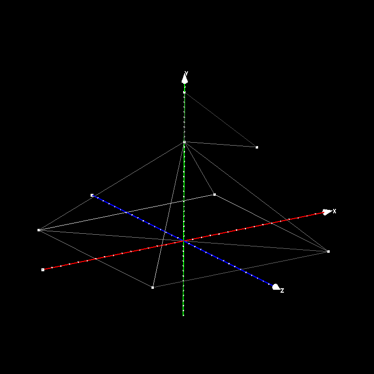
Pyramid with a triangular flag
Do this project alone or in groups of two, as you prefer. You can use Piazza to help pair yourselves up.
In this assignment you will learn about the most widely used way to represent surfaces for graphics: triangle meshes. A triangle mesh is basically just a collection of triangles in 3D, but the key thing that makes it a mesh rather than just a bag of triangles is that the triangles are connected to one another to form a seamless surface. The textbook and lecture slides discuss the data structures used for storing and manipulating triangle meshes, and in this assignment we will work with the simplest kind of structure: a shared-vertex triangle mesh, also known as an indexed triangle mesh.
Your job in this assignment is to write a simple mesh generation and processing utility that is capable of building triangle meshes to approximate some simple curved surfaces, and also can add some information to existing meshes. It reads and writes meshes stored in the popular OBJ file format, a text format with one line for each vertex and face in the mesh.
The written part of this assignment is a warmup for generating more complex meshes. Suppose we wish to generate a mesh (with just vertex positions, no normals or texture coordinates) for a square pyramid (like the one at Giza). The base is a square in the x-z plane, going from -1 to 1 on each axis and the apex is at (0,1,0). Let us now add a triangular flag to our pyramid. We would like the base of the flag to be at the apex of the pyramid and the top to reach a height of 1.5 vertically above. Orient the flag in the positive x-z direction and make it stretch out, 0.5 units away from the center, terminating at the same height as the base. Write out:
The answer consists of 21 floating point numbers (3D coordinates of the vertices) and 21 integers (indices into the list of vertices, 3 for each triangle).
To test out your solution, type it into a text file with the vertices, one per line, and then the triangles, also one per line. Precede each vertex with "v" and each triangle with "f". Note that the indices for the vertices, making up a particular triangle face, should be listed in a counter-clockwise order as viewed from the outside of the given mesh. And one more thing: add one to all the vertex indices, so that the count starting from 1. (Caution! this is not the same as what we do in the data structures inside the program!) For example, a single triangle in the x-z plane, facing towards +y is:
v 0 0 0
v 0 0 1
v 1 0 0
f 1 2 3
This text file is now an OBJ file!
Once you are done making the necessary modifications the final mesh should be the same as the one in the following figure.
Read the completed file into one of the mesh viewers described below, take a couple of screen shots to show that it works, and include them with your writeup.
The OBJ files written by the framework are a little more complicated because they can contain additional data at the vertices: normals and texture coordinates.
The utility "meshgen" is a mesh-generation program that runs at the command line. Its usage is:
  meshgen [-n] [-m] [-r] sphere|cylinder|torus|cube -o <outfile>.obj
  meshgen [-nv]  -f <infile>.obj -o <outfile>.obj
The first required argument is the mesh specifier, and the second is the output filename. If the mesh specifier is one of the fixed strings "sphere", "cylinder", "cube", or "torus", a triangle mesh is generated that approximates that shape, where the number of triangles generated is controlled by the optional -n and -m options (details below), and written to the output file.
A triangle mesh that is an approximation of a smooth surface should have normal vectors stored at the vertices that indicate the direction normal to the exact surface at that point. When generating the predefined shapes, you generate points that are on the surface, and for each you should also calculate the normal vector that is perpendicular to the surface at that point.
If the mesh specifier is -f followed by the name of an OBJ file, the mesh in that file is read. If the -nv flag is given, any vertex normals are discarded and new vertex normals appropriate for a smooth surface are computed from the triangle geometry as described below. Finally, the mesh is writen to the output file.
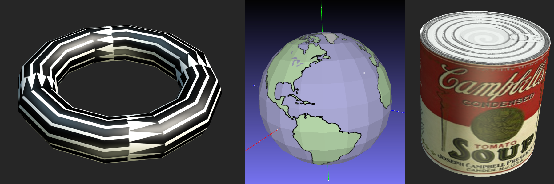
The cylinder has radius 1 and height 2 and is centered at the origin; its axis is aligned with the y axis. It is tesselated with n divisions around the outer surface. The two ends of the cylinder are closed by disc-shaped caps. The vertices around the rims of the cylinder are duplicated to allow discontinuities in the normals and texture coordinates. Each cap consists of one set of the duplicated vertices around the appropriate rim as well as a single point where the cap meets the y axis. This point is incorporated into each triangle in the cap.
Texture coordinates on the outer surface are like the sphere in u, running from 0 to 1 in a counterclockwise direction as viewed from the +y direction, and run from 0 to 0.5 in v, increasing in the +y direction. The texture coordinates for the two caps are circles inscribed in the upper-left (for the -y cap) and upper-right (for the +y cap) quadrants of the unit square, with the +u direction corresponding to the +x direction in 3D space, and the v direction arranged to keep the texture right-reading. We have provided a partial implementation of the cylinder.
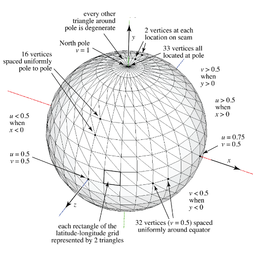
The sphere has radius 1 and is centered at the origin in 3D coordinates. It is tesselated in latitude-longitude fashion, with n divisions around the equator and m divisions from pole to pole along each line of longitude. The North pole is at (0,1,0), the South pole at (0,-1,0), and points on the Greenwich meridian have coordinates (0,y,z) with (z > 0). The mesh is generated with vertex normals that are normal to the exact sphere, and with texture coordinates (u,v) where u depends only on longitude, with (u=0) at longitude 180 degree West and u=1 at 180 degrees East, and v depends only on latitude, with (v=0) at the South Pole and (v=1) at the North pole. Each quadrilateral formed by two adjacent longitude lines and two adjacent latitude lines is divided on the diagonal to form two triangles. The vertices along the 180th meridian are duplicated: one vertex has texture coordinate (u=0) and the other has texture coordinate (u=1), to enable correct wrapping of a tileable texture image across the seam. The vertices at the poles are duplicated (n+1) times, to enable nearly-appropriate texture in the row of triangles adjacent to the pole. You may have noticed that the triangles get compressed near the poles. An alternative tesselation approach can be used to create an isotropic mesh (See icosphere for more details. The implementation is left as an extra credit exercise for those who wish to explore this further).

A torus is a doughnut-shaped surface defined by a major radius, affecting the size of the hole, and a minor radius, affecting the thickness of the ring. Your code should create a torus with major radius 1 and minor radius r (controlled by the -r flag with a default of 0.25). Its u coordinates are like the sphere, and the v coordinate runs from 0 to 1 with a seam on the inside of the torus, with the direction arranged so that the texture is right-reading from the outside. Like the sphere it has a seam on the -z half of the y-z plane, and it has a similar seam around the inside of the tube; vertices along each seam are duplicated twofold and a single vertex, at the position (0, 0, -1+r), is duplicated fourfold.

For a mesh that has vertex positions and triangles, but no vertex normals, one often wants to compute vertex normals so that the mesh can appear smooth. But since the original surface, if there even was one, is forgotten, we need some way to make up plausible normals. There are a number of ways to do this, and we'll use a simple one for this assignment: the normal at a vertex is the average of the geometric normals of the triangles that share this vertex.
Your first thought might be to do this as a loop over vertices, with an inner loop over the triangles that share that vertex:
   for each vertex v
      normal[v] = (0,0,0)
      for each triangle t around v
         normal[v] += normal of triangle t
      normal[v].normalize()
With the appropriate data structures, this is possible, but in our case there's no efficient way to do the inner loop: our data structure tells us what vertices belong to a triangle, but the only way to find triangles that belong to a vertex is to search through the whole list of triangles. This is possible but would be quadratic in the mesh size, which is bad news for large meshes.
However, it's simple to do it with the loops interchanged:
   for each vertex v
      normal[v] = (0,0,0)
   for each triangle t
      for each vertex v around t
         normal[v] += normal of triangle t
   for each vertex v
      normal[v].normalize()
This way the inner loop can efficiently visit just the necessary vertices. Nifty!
You should compute normals whenever the -nv flag is turned on; the logic to do this is already in the framework.
The framework is available on a public Git repository: https://github.com/CornellCS4620/Framework.git
If you have not used Git before, you can follow the tutorial here, or ask a TA for assistance. Once you have the code set up on your local machine, we recommend that you create a new branch (named, for example, my-solution), and commit all changes you make to that branch. When releasing future assignments, we will ask you to pull from our updated repository onto your master branch; creating your own solution branch will avoid the headaches of merge conflicts. We encourage you to use version control though we request that you refrain from publicly sharing your class repository.
We have marked all the functions or parts of the functions you need to complete in with TODO#A1 in the source code. To see all these TODO#A1 annotations in Eclipse, select Search menu, then File Search and type TODO#A1 TODO's in Eclipse can be viewed through the Task List as well. You should only need to modify those the sections marked with TODO unless you want to add other cool mesh generators for extra credit (in which case look at cs4620.util.MeshGen's switch block). All other functionality has been implemented.
The following video contains a walkthrough for setting up your repository, importing into Eclipse, running your code, and viewing the results. The tutorial assumes that you have already installed a git command-line tool as well as the Eclipse IDE.
Since your program just writes a file full of inscrutable numbers, you need some way to look at the results. For this you can use MeshLab. Please refer to the notes from lecture on Sept 3rd for more information about how to get MeshLab and how to use it to load an OBJ mesh and find out what it contains. (Here are a few more programs that might be worth checking out: Blender, ObjViewer, p3d.in ). Warning: Blender discards the normals stored in the OBJ file and as such is not a good tool to check whether your normals are correct. Caution: Blender by default will rotate your mesh by 90 degrees around the x axis so that it displays right way up in Blender's z-is-up world.
Download and unpack the following archive: MeshesTestData.zip
Submit a zip file containing your solution using CMS
You should include a readme in your zip that contains:
Separately submit a zip file containing your paper and pencil on CMS. The solution for the paper and pencil parts of the homework will be done alone, and not in pairs. Please turn that in separately at the appropriate place in CMS.