Assignments
PA4: Ray 2 (Due Tue Nov. 25)
assignment handout | test scenes (v3)
Setting up
Setup is exactly the same as for ray1. The comprehensive setup guide can be found here. Make sure you download the new test scenes, however.
In the Pipeline assignment, you probably found the Matrix4f class to be pretty useful. You'll want something similar to handle transformations for Ray 2. Here is an equivalent Matrix4 class suited to the ray.math package. Just drop it in the ray/math directory.
11/11 9pm - Version 3 of the test-scenes archive contains the XML test scenes (with two more for anti-aliasing), solution images (re-named so you don't have to worry about overwriting them), and a compare.html file to compare your renderings to the solution side-by-side. The solution renderings were done with a depth limit of 12 and an attenuation limit of 0.01. The slowest one was tableau.xml, which took almost 3 minutes. If you're doing glass, Test4-glass.xml took almost 6 minutes.
FAQ:
-
How long should rendering take for the test scenes?
If it's taking longer than 10 minutes for any of them, you may be doing something algorithmically incorrect - or your computer might just be very slow :) We've posted the times for our solution. These were ran on a 2.4GHz Core2 with 2GB of RAM. The recursion depth limit was 12, attenuation cutoff was 0.01, and maximum primitives per bounding volume leaf was 10 (it's OK to hard code these).
-
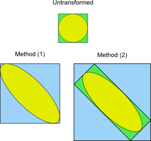
If I put a transformed surface into an axis aligned box, how do I calculate the new maximum and minimum points?
You have two options. You can either (1) figure out the bounding box for the transformed geometry, or (2) transform the old bounding box (with the surface's transformation) and put a bounding box around that. Either approach is fine, but (1) will yield tighter bounds (and fully correct implementations will earn some starred credit).
-
Can we always assume that the transformations are going to be in the order Translate, Rotate, Scale and that there is only going to be one of each type?
You can’t assume either of those. Your code should be able to build up an arbitrary chain of transformations. If the input is:
  <translate> 0 0.5 0 </translate>
  <rotate> -30 10 -20 </rotate>
  <scale> 1 0.5 1 </scale>
Then for any point p, it should get transformed into:p’ = T(0,0.5,0) * Rz(-20) * Ry(10) * Rx(-30) * S(1,0.5,1) * p
Where T(x,y,z) creates a transformation matrix that translates by (x,y,z), and similarly for the other functions. And if below those transforms there was another <translate> 1 2 3 </translate>, it should then become:p’ = T(0,0.5,0) * Rz(-20) * Ry(10) * Rx(-30) * S(1,0.5,1) * T(1,2,3) * p
So the XML-order corresponds to the matrix-composition order (but is backwards with regards to logical-transformation order). Just like how OpenGL and the modeler work. You'll want to take advantage of the Matrix4 class. -
How should I decide which axis to split on?
You should split along the box's longest axis. So if a box is much wider than it is tall or deep, split along X. This avoids very thin/flat boxes, which is good for numerical stability.
-
Do I need to worry about the glass scenes?
Only if you're doing the glass extension. Otherwise, you can ignore "glass-ball.xml" and "Test4-glass.xml". But glass is one of the coolest looking ray-tracing effects, so you're really missing out if you don't :)
-
Where is the framework code?
The framework for this is just the ray1 solution. You can use ours (on CMS under 'Extras'), but you are encouraged to use your own ray1 solution (but make sure it is correct, of course).
PA3: Pipeline (Due Tue Oct. 28)
assignment handout | framework codeSetting up & Running the framework
- Extract the framework ZIP file into a project root folder, so it's laid out as follows:
   <project root>
	data/
	dlls/
	jars/
	pipeline/
- Create the project in Eclipse: File -> New -> Java Project -> Choose "Create project from existing source" and set "Directory" to <project root>. Name it something, such as "pipeline".
- Right click on the project in the package explorer -> Build Path -> Configure Build Path… -> Java Build Path -> Libraries -> Add JARs… -> expand your project, expand "jars", highlight all three, and click OK.
- Make a Run configuration for MainFrame
- Under the Run... menu, go to the Arguments tab.
- In the VM Arguments pane, put the following:
-Djava.library.path=./dlls/
This tells java how to find the JOGL (Java OpenGL, pronounced "joggle") dlls it needs to run the program.
FAQ:
-
Why doesn't my smooth shading match OpenGL window for the cube? (Courtesy of Manuel Vargas)
If your computer has an ATI graphics card, you might get a mismatch like this for the cube:

That's OK. It's just that the graphics card is tesselating the polygon differently, so that's why the highlight shows up badly in a different way. However, all other scenes should still match OpenGL. And to be safe, you may want to run your code on another computer with a different graphics card.
-
Can't we have a nicer looking bunny?
OK, I admit, no one asked this. But our pipeline has enough vertex throughput to handle more triangles to better show off fragment shading and reflection mapping. Here is a 10,000 triangle bunny:
bunny10k.zip. If you put it in thedatadirectory and add it to the list atMainFrame.java:148you can have a more recognizable bunny. -
Can we see some screenshots of correct implementations for reference?
Sure: 1 2 3 4 5 (updated) 6 (updated again)
-
How do I run this in Linux or OSX?
Linux: Download the .so files and put them in the "dlls" directory. OSX: Download the .jnlib files and put them in the "dlls" directory.
-
Why won't the framework compile under my 64-bit operating system?
Because the libraries we provide are compiled for 32-bit, which is the mode in use in the lab. You can probably get it to work by downloading the proper compile of the Jogl library and making a few changes to the framework. If you get this to work, let us know how it went and we'll post some more specifics.
PA2: Modeler (Due Oct. 10th)
assignment handout | framework code | user guideSetting up & Running the framework
- Extract the framework ZIP file into a project root folder, so it's laid out as follows:
   <project root>
	dlls/
	jars/
	icons/
	modeler/
- Create the project in Eclipse: File -> New -> Java Project -> Choose "Create project from existing source" and set "Directory" to <project root>. Name it something, such as "PA2".
- Right click on the project in the package explorer -> Build Path -> Configure Build Path… -> Java Build Path -> Libraries -> Add JARs… -> expand your project, expand "jars", highlight all three, and click OK.
- Make a Run configuration for MainFrame
- Under the Run... menu, go to the Arguments tab.
- In the VM Arguments pane, put the following:
-Djava.library.path=./dlls/
This tells java how to find the JOGL (Java OpenGL, pronounced "joggle") dlls it needs to run the program.
FAQ:
-
Manipulator mouse-following clarifications
In the hand-out, it mentions that the translation and non-uniform manipulations should follow the mouse pixel-for-pixel. This would be required if you were doing manipulators for orthographic views, but you're not. For the perspective view the follows-condition is a bit more relaxed, although less intuitive: Let's call the eye ray corresponding to the current mouse position the "mouse ray." Also, let's call the intersection (or, nearest-point pseudo-intersection) of the mouse ray to the plane (or, axis) of manipulation the "follow point". So when the user drags the mouse, the follow point moves. Then, the object must follow the follow point, not the mouse position.
For orthographic views, the follow point happens to correspond directly to the cursor position. With perspective projection, it's clearly not an exact correspondance. Thus, while the manipulation should follow the mouse cursor pretty closely - the discrepancy should be barely noticeable near the view center - it does not need to be pixel-for-pixel exact. Using the method outlined in section 4.3 of the hand-out will yield such a following.
-
Do I need to handle the flipped camera for manipulators?
Nope - as long as your manipulators work when "Camera Flip" is unchecked, you're good.
-
Some triangles seem to be drawing backwards - why is this?
The order in which you send your vertices affects which side gets drawn. Typically, you only need to draw one side of a triangle (especially for closed surfaces), so if you know a triangle is facing away from you, you can save time and not draw it at all. This is called "back-face culling". But how do you know which side of a triangle is the "back" face? By default (and for this project), OpenGL uses the right hand rule, so you should send your vertices in counter-clockwise order (point your right-hand thumb in the desired front-facing direction, and then wrapping your fingers will sweep the vertices in counter-clockwise order). For example, say your triangle was like this:
A
| \
|  \
B---C
If the front face is facing out of the screen, then you should send the vertices in the following order: ABC. Of course, CAB and BCA also work. If the front face is facing into the screen, in which case this triangle should not be drawn at all, then you would send vertices in the opposite order (CBA, BAC, or ACB). -
How do I run this in Linux or OSX?
Linux: Download the .so files and put them in the "dlls" directory. OSX: Download the .jnlib files and put them in the "dlls" directory.
-
Why won't the framework compile under my 64-bit operating system?
Because the libraries we provide are compiled for 32-bit, which is the mode in use in the lab. You can probably get it to work by downloading the proper compile of the Jogl library and making a few changes to the framework. If you get this to work, let us know how it went and we'll post some more specifics.
PA1: Ray 1 (Due Sept. 16th)
assignment handout | framework code (v.2) | sample input and images (v.2) | Eclipse guideNote that the sample scenes are just to get you started, and they do not comprise an exaustive test of your program. You will want to devise more scenes of your own for debugging and to test additional cases.
FAQ:
- Q: How do I get this thing to compile and
work?
A: We have written a brief guide to help you get set up in Eclipse. We can give some advice about other IDEs, but since we all use Eclipse we may not be that much help.
- Q: Which Eclipse package should I download?
A: Go here and download the second one, Eclipse IDE for Java Developers (85 MB).
- Q: What is this business
with
viewUpandprojNormaland u, v, and w?
A: Take a look at this revised section of Chapter 2. It expands on the construction of a basis from two vectors. A project-specific remark: w is the image plane normal, specified byprojNormalin the input. The view direction is not used in constructing the basis; it is used to position the origin of (u, v) coordinates on the image plane. In a "normal" perspective view these two vectors are collinear; it is for oblique views (e.g.wire-box-sper.xml) that the two separate vectors are actually used.