CS 3410 Logisim Tips: How to make life easier
Tip #1: Connecting splitters to gates (and splitters to splitters)
Some students connect wires from splitters to gates one by one, which becomes tedious when the number of inputs gets large.
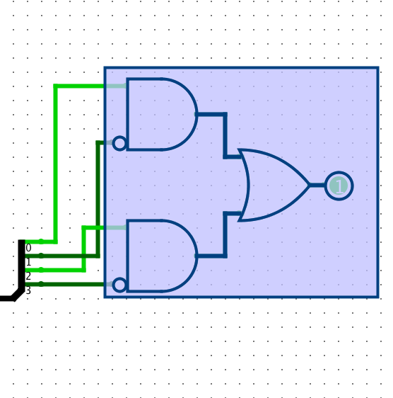
| First, connect the gate and splitter. Then, drag the gate to make the wires. | |
 The tedious way to do this |
 The easy way to do this |
| This trick becomes very useful when you have a lot of inputs (like 32 inputs). You can also do this to connect splitters and splitters. | |
Alternatively, if you do now want to have wires between your splitter and the gate, you can just connect them and not drag the gate.
Tip #2: Negating an input to a gate
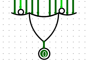
Adding circles instead of not gates can make your circuit neater.
| Instead of adding a not gate, you can add little circles to negate an input. | |
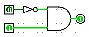 Adding a not gate |
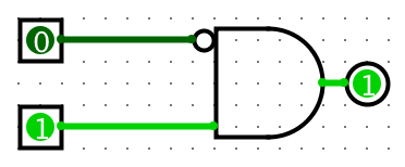 Adding a circle |
| The above two circuits are equivalent. Note that you can add these circles for any type of logic gate. | |
To add the circles, follow the following steps:
1) Make sure you are in the "Edit selection and add wires" mode (just click on the black arrow at the top left of the window).
2) Click on the gate that you want to add the circle to.
3) In the properties section of the gate (at the bottom left section of your window), choose which input to negate.
If you don't want to add the circles, you don't have to. It is your choice to make in the end.
Tip #3: Changing the appeareance of logic gates
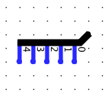
You can change the facing attribute (North, South, East, or West) and the number of inputs to change the appearance (and the functionality) of the gate.
| Some example appearances of logic gates. | |
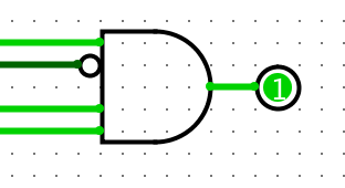 4-input AND gate facing east |
 10-input OR gate facing south |
| Note: You can also edit the "Data Bits" attribute to change the number of bits each input will have (above examples have 1-bit inputs). | |
To change the appearances, follow the following steps:
1) Make sure you are in the "Edit selection and add wires" mode (just click on the black arrow at the top left of the window).
2) Click on the gate that you want to change the appearance of.
3) In the properties section of the gate (at the bottom left section of your window), edit the "Facing" and the "Appearance" as you wish.
Tip #4: Reversing the distribution of splitters
Sometimes, you would want to reverse the distribution of splitters.
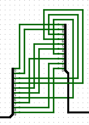
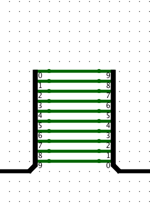
| Right click on a splitter and choose distribute ascending/descending to change distrubtion. | |
 The tedious way to do this |
 The easy way to do this |
| This tip will be particularly useful when you have a big splitter (like for splitters that have 32 fan outs.) | |
Tip #5: Changing the appeareance of splitters
You can change the facing attribute (North, South, East, or West) and the appearance attribute (Left-Handed, Right-Handed, Centered, or Legacy) to change how the splitter looks.
| Some example appearances of splitters. | |
 Right-handed splitter facing south |
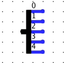 Centered splitter facing east |
| Try playing around with these appearances to choose the appearance that fits your circuit the best. | |
To change the appearances, follow the following steps:
1) Make sure you are in the "Edit selection and add wires" mode (just click on the black arrow at the top left of the window).
2) Click on the splitter that you want to change the appearance of.
3) In the properties section of the splitter (at the bottom left section of your window), edit the "Facing" and the "Appearance" as you wish.
Tip #6: Ticking the clock
Some projects involve usage of clocks.
| There are mainly two ways to tick the clock. | |
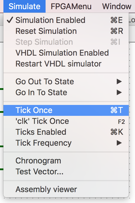 Press command (control) T to tick once. |
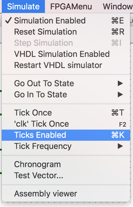 Press command (control) K to tick repeatedly. |
| When you do command (control) K, you can also change the tick frequency under the simulate tab (right under "Ticks Enabled"). | |
Tip #7: Adding names to your input and output by double clicking
Having names for your inputs and outputs are important to keep your circuit readable and organized.
Note: Make sure you are in the "Edit selection and add wires" mode (just click on the black arrow at the top left of the window).
| After adding an input, you can double click on it to add a label. | |
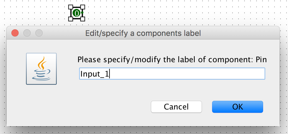 Double click on the input |
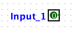 Input now has label |
| Double clicking also works with outputs, logic gates, registers, subcircuits etc. | |
Tip #8: Moving multiple components at once
Sometimes, you might want to move multiple components at once. Instead of moving them one by one, try highlighting them all to make life easier.
| Example: Let's say you wanted to move this combination of logic gates down. | |
 First, highlight the components that you want to move. |
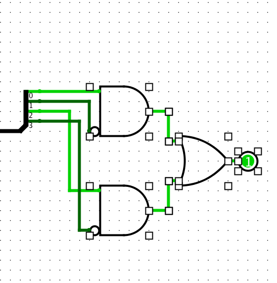 Then, drag it down to move them all at once. |
| Also, you can press command (control) A to highlight every component in a circuit. | |
Tip #9: If you make a mistake, you can "undo" your mistake
Sometimes, you accidentally move things and make the circuit less neat.
| Let's say you accidentally moved this splitter, and it looks very complicated. | |
 Whoops, you accidentally moved the right splitter, and it's a mess. |
 Just press command (control) Z to undo your mistake. |
| You can press command (control) Z multiple times to undo multiple of your most recent edits. | |
Tip #10: Changing the format of your input and output.
You can choose the "radix" attribute of input/output to be binary, octal, signed decimal, unsigned decimal, or hexadecimal.
| The default setting is binary, but you can change that as you wish. | |
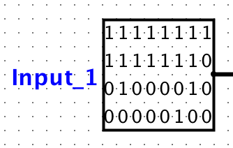 Binary representation of a 32-bit input. |
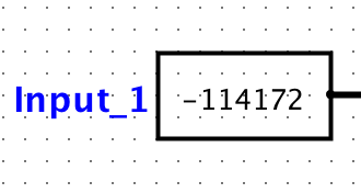 Signed decimal representation of the input on the left. |
| You can change the format like this for outputs as well. | |
To change the appearances, follow the following steps:
1) Make sure you are in the "Edit selection and add wires" mode (just click on the black arrow at the top left of the window).
2) Click on the input/output that you want to change the format of.
3) In the properties section of the gate (at the bottom left section of your window), edit the "Radix" attribute as you wish.
Tip #11: Going into a subcircuit and going back to the main circuit
Sometimes, you want to look into a subcircuit to know what's going on in it.
| Double clicking and command (control) left arrow will make this easy. | |
 Double click on the subcircuit to go into the subcircuit. |
 Press command (control) and left arrow to go back to the main (parent) circuit. |
| You can also press command (control) and right arrow to go into the most recently visited subcircuit. | |
© 2019 Akira Shindo