Lab 1: Introduction to Logisim
CS 3410 Spring 2018
Pairing: You are welcome to work with someone in your lab section on this lab but you must each submit your own solution to CMSX.
Due: This lab is to be completed entirely in Lab Section. If you are unable to finish for whatever reason, please go to office hours on Sunday. After you are done, submit a single file with your XOR and adder subcircuits.
Logisim
Welcome to Logisim! Logisim is a logic simulator that allows you to design and simulate digital circuits using a graphical user interface.
Logisim comes with libraries containing basic gates, memory chips, multiplexers and decoders, and other simple components. In later assignments you
will use many of these components to build your final CPU.
For this lab, we will guide you through the process of creating your first adder in Logisim.
Step 0: Obtaining Logisim
To get started, follow these instructions to get a copy of Logisim on your working machine.
-
Logisim requires Java 5 or later. If you do not already have it on your computer, Java is available from java.sun.com.
-
Download Logisim from CS 3410 Resources page. This is a Cornell snapshot of Logisim Evolution. It comes as a jar file that will work on every operating system as long as you have java installed. Please use this snapshot so that we are all using the same version of Logisim for the entire semester. Make sure the version number is the current version, 2.13.20.5 before you begin working. Logisim will automatically check for any additional updates from us, so you should only need to download one time.
-
To execute the program: On Windows and OS X systems, you will be able to start Logisim by double-clicking the jar file. If that doesn't work, or if you use Linux or Solaris, you can type
java -jar logisim-evolution.jarat the command line. For OS X there is a wrapped version of the jar file, there for convenience and aesthetics, but it does nothing more than launch the jar equivalent.
Step 1: The beginner's guide
Logisim is a simple tool to use, most of the features you will need are well documented in the reference document. You can obtain the guide from the Logisim Documentation page. Start with the Beginner's tutorial under 2.7.x documentation. It will show you around the graphical interface, as well as guide you through a simple XOR circuit. Work through the XOR circuit, ask your TA to check this box when you are done.
Checkoff: Show your XOR Circuit to your TA
Step 2: Add4
Now that you have implemented your first XOR gate in Logisim, let us work on a more complicated circuit -- a 4-bit adder. You may find some of the terms, such as two's complement numbers, are difficult to understand. Don't panic. You will not need to understand it in order to finish this lab. Again, the purpose of lab1 is to get you familiar with the software environment that you will be working in for this class in the next few weeks.
Definition (excerpt from Wikipedia article):
A full adder adds binary numbers and accounts for values carried in as well as out.
A one-bit full adder adds three one-bit numbers, often written as A, B, and Cin;
A and B are the operands, and Cin is a bit carried in (in theory from a past addition).
The full-adder is usually a component in a cascade of adders, which add 8, 16, 32, etc. binary numbers.
In the notation below, A[4] denotes that the input is named "A" and is 4 bits wide. The input should not be named "A[4]". Another incorrect approach is to create four separate inputs, each named A or some variant. Instead, the correct approach is to create a single input and make it 4 bits wide by changing the "Data Bits" attribute of the input. The attributes appear on the lower left pane of the Logisim window when the input is selected.
| Add4: | C = A + B + Cin; Cout = overflow |
| Inputs: | A[4], B[4], Cin |
| Outputs: | C[4], Cout |
The output C is computed by adding A, B, and Cin. A, B, and C are signed two's complement numbers. If overflow occurs, the output Cout should be asserted. In such cases, the output C should correspond to the value computed if all overflow errors are ignored.
Sub-circuits
Use sub-circuits to make wiring easier by building a 1-bit adder, then a 4-bit adder, and then eventually a 32-bit adder. Using a sub-circuit in Logisim is equivalent to writing a function and using it multiple times when coding. To create a new circuit, select "Project->Add Circuit..." from the toolbar. To use a circuit (A) as a sub-circuit of another (B), double-click on circuit B on the left pane of Logisim (the Explorer Pane). A magnifying glass appears on circuit B's icon, and now the contents of circuit B appear on the right pane (the Canvas). Click once on circuit A in the Explorer Pane, then click anywhere in the canvas to place an instance of circuit A as a sub-circuit of circuit B. As one would expect, any time circuit A is updated, all instances of it appearing in circuit B will change their operation in the same way.
For more information on sub-circuits, the corresponding documentation pages are useful.
Build 1-bit adder
A truth table shows how a logic circuit's output responds to various combinations of inputs. For example, if all inputs to a full adder are '0's, the outputs will also be '0'. Complete the truth table below.
| Inputs | Outputs | |||
|---|---|---|---|---|
| A | B | Cin | Cout | S |
| 0 | 0 | 0 | 0 | 0 |
| 1 | 0 | 0 | ||
| 0 | 1 | 0 | ||
| 1 | 1 | 0 | ||
| 0 | 0 | 1 | ||
| 1 | 0 | 1 | ||
| 0 | 1 | 1 | ||
| 1 | 1 | 1 | ||
The truth table above can also be expressed using boolean algebra.
| S = A xor B xor Cin |
| Cout = (A and B) or (Cin and (A xor B)) |
A technique called Karnaugh map, named after Maurice Karnaugh, a telecommunication engineer at Bell labs in 1953, will make the conversion from truth table to boolean algebra very simple. You may peruse the Wikipedia article on Karnaugh maps if you are curious, but this is not necessary at this point.
For now, let us move on to implement the 1-bit adder in Logisim. Create the following circuit in Logisim, then save it as an appropriately-named circuit.

Checkoff: Show your 1-bit adder circuit to your TA
Build 4-bit adder
A 4-bit adder is as simple as cascading 4 one-bit adders together, with carry-out from one adder fed into the carry-in of the other adder. Later on in the course, we will discuss why this may not be the fastest implementation (for the interested student: why?), but it will serve our needs just fine for now.
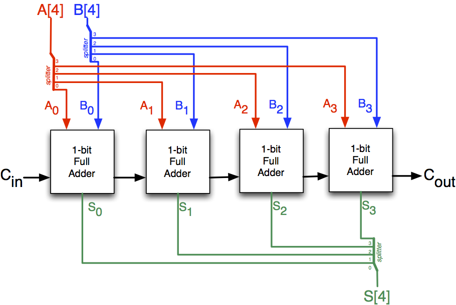
Create the 4-bit adder in Logisim, re-using the 1-bit adder as a sub-circuit. Ask TA for help if you are unsure of what to do. Save your work in an appropriately-named circuit.
Hint 1: use splitters
Logisim provides a component called splitter in the wiring library. It creates a correspondence between a multi-bit value and several separate subsets of those bits. Despite the name, you may use the splitter as a "bundler" as well, joining multiple individual bits into a multi-bit value. You may want to use splitter in your 4-bit adder to help you manage the input and output values. For more information, please refer to the help page for the Splitter.
Hint 2: use probes
Probes are great for debugging circuits. You can connect them to the in/out busses and set to display values in base 10 for quick checking. Refer to the help page for the Probe for more information.
Hint 3: use tunnels
Tunnels are not necessary for this lab and should be used sparingly; excessive use of tunnels will lead to docked points on future assignments. That said, they become important when the size of your circuit gets bigger. A "tunnel" acts like a wire that binds points with the same label together, except that the wire is not explicitly displayed. This is helpful to keep your circuit clean and organized. For more information, refer to the help page for the Tunnel.
Checkoff: Show your 4-bit adder circuit to your TA
Optional: Use your 4 bit adder to create an 8 bit adder.
Step 3: Happy Dance!
Congratulations! You have successfully finished Lab 1. Please make
sure you have demonstrated your working adder to your TA and submitted
your .circ file to CMSX.
We will build more circuits with Logisim in the following weeks. For a bit of
fun, check out this
youtube video to see an example of a cool project created using Logisim.