8b/10b encoding was proposed by Albert X. Widmer and Peter A. Franaszek of IBM Corporation in 1983. The code defines the mapping from a 8-bit byte (256 unique data words) and an additional 12 special (or K) characters into a 10-bit symbol, hence the name 8b/10b encoding. It has been widely used in high speed serial communication standards that need a run-length limited, charge balanced data stream for reliable data transmission and clock recovery. Because of its many feature, the code has been used in the physical layer (PHY) of a number of current and emerging standards, including Fibre Channel, Gigabit Ethernet, and Rapid I/O, to name a few.
In this section, we explain the functionality of the encoder in more details. Your design should implement all the features mentioned in this section. We have borrowed a few terms from the original IBM patent. Understanding them clearly is crucial to a successful implementation of the encoder. The most important terminology to understand for this assignment is disparity.
The code scheme actually partitions the input byte into 5-bit and 3-bit sub-blocks, which in turn are encoded into 6- and 4-bit blocks respectively. The original nomenclature defines the symbols in terms of these sub-blocks. The five input bits are defined as A, B, C, D and E (A is Least Significant Bit) and the 3-bit block is F, G and H (F is LSB). A prefix of D or K is used to distinguish between data and special characters respectively. For example, D31.1 is a data symbol with all ones on the 5-bit block (11111) and a single one as the LSB of the 3-bit block (100) (see Table 1). Note that the 5-bit sub-block precedes the 3-bit sub-block and the ordering (LSB to MSB) is ABCDE_FGH. The encoded sub-blocks are described with lowercase letters a, b, c, d, e, i (i is LSB) and f, g, h, j (j is LSB) respectively, and the ordering is (LSB to MSB) jhgf_iedcba. See Appendix A for the mapping between input bytes and output bits.
| Din[7:0] | DOut [9:0] | |||||||||||||||||||
| 7 | 6 | 5 | 4 | 3 | 2 | 1 | 0 | RD (prior) | 0 | 1 | 2 | 3 | 4 | 5 | 6 | 7 | 8 | 9 | RD (after) | |
| H | G | F | E | D | C | B | A | j | h | g | f | i | e | d | c | b | a | |||
| D31.1 | 0 | 0 | 1 | 1 | 1 | 1 | 1 | 1 | +1 | 1 | 0 | 0 | 1 | 0 | 0 | 1 | 0 | 1 | 0 | -1 |
| D31.1 | 0 | 0 | 1 | 1 | 1 | 1 | 1 | 1 | -1 | 1 | 0 | 0 | 1 | 1 | 1 | 0 | 1 | 0 | 1 | +1 |
Table 1: Example Encoding of D31.1 for both running disparity (RD) cases
The encoder assumes a negative RD- (-1) at start up. When a 8-bit data is encoding, the encoder will use the RD- column for encoding. If the 10-bit data been encoded is disparity neutral, the Running Disparity will not be changed and the RD- column will still be used. Otherwise, the Running Disparity will be changed and the RD+ column will be used instead. Similarly, if the current Running Disparity is positive (RD+) and a disparity neutral 10-bit data is encoded, the Running Disparity will still be RD+. Otherwise, it will be changed from RD+ to RD- and the RD- column will be used again.
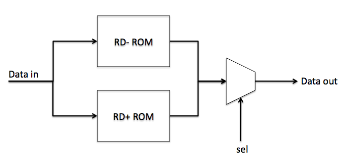
For simplicity, we have provided you with 2 files named RD_MINUS and RD_PLUS. These files can be used by the ROM component in Logisim to implement a hardware lookup table. The contents of these files store the corresponding 8b/10b encoding mappings for when the running disparity is (+1) and (-1).
Please follow the following steps when implementing the encoder. After you have completed a section, check it over with a TA before you proceed to the next section.
| Inputs: | data_in[8], Clock, Reset |
| Outputs: | data_out[10] |
Part 1: Datapath
| Inputs: | data_in[8], sel |
| Outputs: | data_out[10] |
One way to implement the mapping between input symbols and output symbols is by using a hardware lookup table (LUT) using the ROM component in Logisim. The input port to the ROM specifies the address of the word that is accessed. The output port returns the content at the particular address which is specified by the input. The ROM in Logisim is customizable, you may change the input and output bitwidth to fit your need. For this assignment, use an input width of 8 bits and an output width of 10 bits for the ROM files that were provided. We assume in this assignment that, the access time for the ROM is one clock cycle, i.e., the content in the ROM at the address that you specified is available within the same clock cycle.
Part 2: Finite State Machine
| Inputs: | data_in[10], Clock, Reset |
| Outputs: | sel |
The running disparity is maintained by storing the current disparity in a register. Each time an new output symbol is generated, the current disparity should be updated by adding the value stored in the flip-flop with the parity of the output symbol. Note that this operation is completely internal to the encoder, and should be not visible to the external world. You are free to choose how many states you need for the FSM and what state encoding is used. Minimizing the number of bits used to encode states helps with simplifying your circuit.
Part 3: Putting it all together
| Inputs: | data_in[8], Clock, Reset |
| Outputs: | data_out[10] |
Now you may combine the FSM and datapath into the required "Encoder" top-level circuit. Remember to name the inputs and outputs exactly as shown here.
Complexity: The encoder design is not large. If you use more than a handful of components for the datapath or interface, for example, you are probably working too hard. The finite state machine can be done with only a few states, and most of the outputs of the finite state machine part are trivial.
Clock: For debugging, you can put a Logisim "Clock" into your circuit and set Logisim to toggle the clock one step at a time, or automatically at a set frequency. You should a single clock for your entire circuit.
Submit single Logisim project file containing all of your circuits. The top-level circuit should be called "Encoder", and should have the same input and outputs as described above in Part 3.
The Appendix has the entire 8b/10b encode table listed in it. Be smart about using it!
Encoding table sorted by Dxx.pdf
Encoding table sorted by Dy.pdf
For the adventurous, Implement the encoding of K(control) characters in your encoder. To do this, create a separate Logisim circuit within the same project file (.circ file) named "Encoder_bonus". This circuit should have the same inputs and outputs as "Encoder", but with an additional input k_in and additional output k_err.
If k_in is 0, operation should be exactly like the non-bonus encoder, and k_err should always be 0. If k_in is 1, then interpret data_in as a control character, and output the corresponding data_out and k_err = 0 if valid, or any data_out you want and k_err = 1 for an invalid control character.