Lab 0 - Introduction to Logisim
CS3410 Spring 2012
Due: In class
Overview
Welcome to Logisim! Logisim is a logic simulator that allows you design and simulate digital circuit using a graphical user interface.
Logisim comes with libraries containing basic gates, memory chips, multiplexers and decoders, and other simple components. In later assignments you
will use many of these components to build your final CPU.
For this lab, we will guide you through the process of creating your first adder in logisim.
Step 0: Obtaining Logisim
To get started, follow these instructions to get a copy of logisim on your working machine.
1. Logisim requires Java 5 or later. If you do not already have it on your computer, Java is available from java.sun.com.
2. Download Logisim from CS3410 class webpage
or from logisim SourceForge page. You will have three choices of release to download.
- A .jar file - runs on any platform, though not necessarily conveniently.
- A MacOS .tar.gz file
- A Windows .exe file
A jar file is probably the easiest on the deal with, but you could always choose the release specific to your platform.
3. To execute the program:
- With the generic .jar file: On Windows and MacOS systems, you will likely be able to start Logisim by double-clicking the JAR file. If that doesn't work, or if you use Linux or Solaris, you can type ``java -jar logisim-XX.jar'' at the command line.
- With the MacOS X version: Once the downloaded .tar.gz version is uncompressed (this will likely happen automatically), just double-click the Logisim icon to start. You may want to place the icon into the Applications folder.
- With the Windows version: Just double-click the Logisim icon. You may want to create a shortcut on the desktop and/or in the Start menu to make starting Logisim easier.
Step 1: The beginner's guide
Logisim is a simple tool to use, most of the features you will need are well documented in the reference document.
You can obtain the guide from the logisim Documentation page .
Start with the Beginner's tutorial. It will show you way around the graphical interface, as well as
guide you through a simple XOR circuit. Work through the XOR circuit, ask your TA to check this box when you are done.
Checkoff
|
Show your XOR circuit to your TA.
| |
Step 2: Add8
Now you have implemented your first XOR gate in logisim, let us work on a more complicated circuit -- A 8-bit adder.
You may find some of the terms, such as two's complement numbers, are difficult to understand. Don't panic.
You will not need to understand it in order to finish this lab. Again, the purpose of lab0 is to get you familiar
with the software environment that you will be working in for this class in the next few weeks.
Definition (excerpt from wikipedia[1]):
A full adder adds binary numbers and accounts for values carried in as well as out.
A one-bit full adder adds three one-bit numbers, often written as A, B, and Cin;
A and B are the operands, and Cin is a bit carried in (in theory from a past addition).
The full-adder is usually a component in a cascade of adders, which add 8, 16, 32, etc. binary numbers.
| Add8: | C = A + B + Cin; V = overflow |
| Inputs: | A[8], B[8], Cin |
| Outputs: | C[8], V |
The output C is computed by adding A, B, and Cin.
A, B, and C are signed two's complement numbers. If overflow occurs, the output
V should be asserted. In such cases, the output C should correspond to the value computed if
all overflow errors are ignored. Hint: Use sub-components to make wiring easier by building a 1-bit adder, then
a 4-bit adder, and then a 8-bit adder.
Build 1-bit adder
A truth table shows how a logic circuit's output responds to various combinations of inputs. For example, if all inputs
to a full adder are '0's, the outputs will also be '0'. Complete the truth table below.
| Inputs |
Outputs |
| A |
B |
Cin |
Cout |
S |
| 0 |
0 |
0 |
0 |
0 |
| 1 |
0 |
0 |
|
|
| 0 |
1 |
0 |
|
|
| 1 |
1 |
0 |
|
|
| 0 |
0 |
1 |
|
|
| 1 |
0 |
1 |
|
|
| 0 |
1 |
1 |
|
|
| 1 |
1 |
1 |
|
|
The truth table above can also be expressed using boolean algebra.
| S = A xor B xor Cin |
| Cout = (A and B) or (Cin and (A xor B)) |
A technique called Karnaugh map, named after Maurice Karnaugh, a telecommunciation engineer at Bell labs in 1953,
will make the conversion from truth table to boolean algebra very simple. Check out reference [2] at your spare time.
For now, let us move on to implement the 1-bit adder in logisim. Enter the following circuit into logisim, save it as
fulladder1.circ

|
Show your 1-bit adder circuit to your TA.
| |
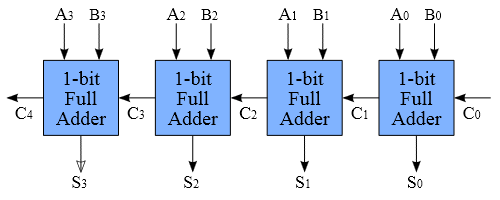
Build 4-bit adder
A 4-bit adder is as simple as cascading 4 one-bit adder together, with carry-out from one adder fed into the carry-in
of the other adder. However, this may not be the fastest way to do it, why?
Enter the 4-bit adder into logisim, try to reuse the circuit you have done for 1-bit adder. Ask TA for help if you are
sure what to do. Save your work in fulladder4.circ
Hint: use splitters
Logisim provides a component called splitter in the base library. It creates a correspondence between a multi-bit value
and several seperate subsets of those bits. Despite the name, you may use the splitter as a "bundler" as well, joining
multiple individual bits into a multi-bit value. You may want to use splitter in your 4-bit adder to help you manage the
input and output values. For more information, please refer to the help page on splitter .
Hint: use probes
Probes are great for debugging circuits. You can connet them to the in/out busses and set to display values in base 10 for quick checking.
Refer to the help page on Probe for more information.
Hint: use tunnels
Tunnels are not neccessary for this lab. But they become important when the size of your circuit gets bigger. A "tunnel" acts like a wire that binds
points with the same label together, except that the wire is not explicitly displayed. This is helpful to keep your circuit clean and organized.
For more information, refer to this page.
|
Show your 4-bit adder circuit to your TA.
| |
Build 8-bit adder
Now let us build a 8-bit adder, by reusing the circuit in fulladder4.circ
|
Show your 8-bit adder circuit to your TA.
| |
Congratulations! You have successfully finished Lab0. Please make sure you have demonstrated your working adder to your TA.
We will build more circuits with logisim in the following weeks. As a fun fact, check out this youtube video to see what amazing work you could do with logisim.
Reference
[1] Full adder: http://en.wikipedia.org/wiki/Adder_(electronics)
[2] Karnaugh map: http://en.wikipedia.org/wiki/Karnaugh_map