Logisim doesn't do a good job of supporting true busses, because it lacks bi-directional pins and the simulator seems to sometimes have trouble with controlled buffers (i.e. tristates) resulting in "E" errors on the bus wires.
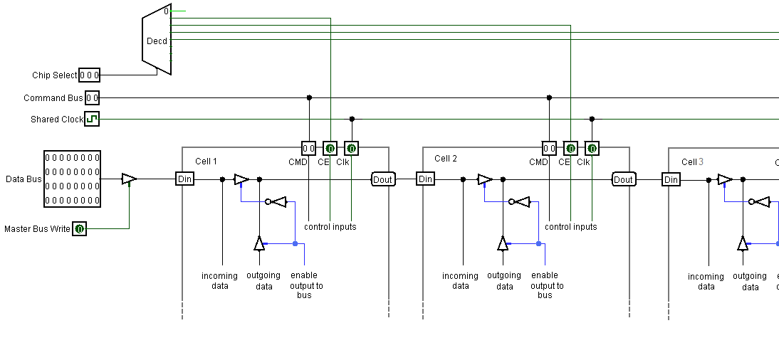
The skeleton circuit QuadCellPlayground circuit we provided looks like this (I've pasted in drawings of the internals of each cell in this drawing):
The read-only parts of the bus (the CMD wires) are simply connected as inputs to each cell. The read/write part of the bus (the data wires) pass through each cell via Din and Dout. At all times, you must enable at most one of the tri-state "controlled buffers". There are four shown in the drawing above: three inside cells, and one master on the left. If Logisim is working properly, the bus wires to the left of the single enabled tristate should be "x", and the wires to the right should have a non-error value.
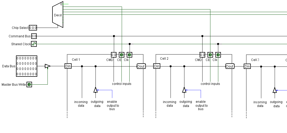
If Logisim is misbehaving, it may produce error values on the bus even though only a single tri-state is enabled. One workaround is to add a tri-state "controlled buffer" inside each cell, like so: